
Parallel input and output axes let a driven shaft occupy a different line from the motor without a separately added chain stage. A simplified rectangle in CAD conceals housing, shaft and motor interference. Refer to the F-series compact parallel shafts guidance. Capture the actual motor fan clearance and gearbox support reach. Mating fit and torque transmission should be verified for the ordered variant.
Use the axis offset deliberately
Inspect radial output loads
Plan assembly and disassembly order
Use the axis offset deliberately
Parallel shaft layouts place input and output on separate but parallel centerlines; the offset may fit a motor beside the frame while keeping the driven shaft on a fixed conveyor elevation.
A simplified rectangle in CAD conceals housing, shaft and motor interference; dimension the input and output centerlines in a common coordinate system.
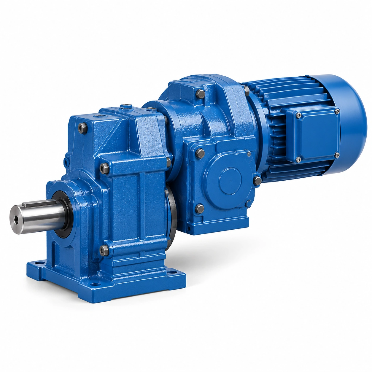
Capture the actual motor fan clearance and gearbox support reach; approve the arrangement with an interference-free three-dimensional envelope; packaging gain disappears if later motor withdrawal requires dismantling the conveyor.
Check the hollow shaft engagement
An FA output bore can receive a driven machine shaft without an external output coupling; the assembly depends on bore tolerance, usable engagement length, keys and retention features.
A nominal bore diameter does not establish a safe shaft-to-hub connection; supply driven shaft diameter, key detail, shoulder positions and engagement length.
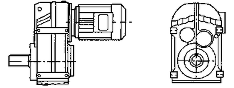
Compare the F-series hollow-output drawing with the machine shaft manufacturing drawing; mating fit and torque transmission should be verified for the ordered variant; a loose or short engagement can cause fretting before the gearbox reaches its rated torque.
Design the torque reaction restraint
A shaft-mounted gearbox needs a separate path to resist housing rotation under output torque; a reaction arm can allow controlled movement from thermal expansion or shaft deflection.
Rigidly locking every degree of freedom can put unwanted loads into the reducer bearings; show torque direction, arm length, joint positions and permissible angular movement.
Measure the intended reaction attachment location on the supporting frame; approve a restrained but non-overconstrained layout against the supplier installation notes; a missing or incorrectly aligned restraint can move the entire housing.
Compare foot and flange alternatives
F and FF arrangements support the weight and torque through different structural points; a flange may free floor area while requiring a stiff machined interface in the machine side plate.
Picking a flange for compactness alone may overload a thin cover or shell; check mounting plate stiffness and specified register tolerance.
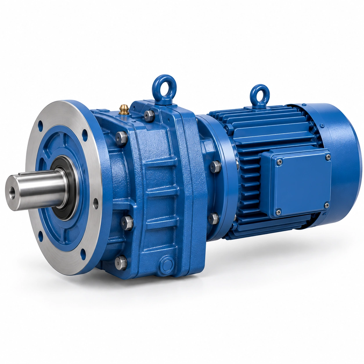
Include support reaction diagrams and the fastening layout for the actual assembly; the selected mount should keep alignment within equipment-approved limits; structural deflection produces effects that a product photograph cannot predict.
Inspect radial output loads
A sprocket or pulley on an external output stub produces overhung load; bearing load depends on side force and its distance from the nearest bearing.
Matching gearbox torque does not demonstrate allowable sprocket pull; calculate tangential chain or belt load and shaft lever arm under worst duty.
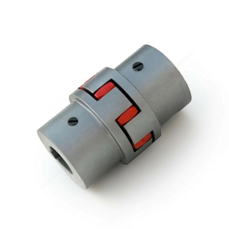
Request permissible radial force at the actual output speed and force location; approval should identify bearing life basis and any external support required; ignoring overhung load can make a compact drive a maintenance liability.
Bearing load depends on side force and its distance from the nearest bearing. Matching gearbox torque does not demonstrate allowable sprocket pull. Examine the F-series compact parallel shafts layout example. Request permissible radial force at the actual output speed and force location. Approval should identify bearing life basis and any external support required.
Build the seal-removal clearance
A reducer tucked behind a guard may prevent output-seal replacement without dismantling major structures; a side plate placed millimeters from a seal cover can make normal maintenance impossible.
The machine owner bears the lost production time when access was omitted; overlay the removal path of seal covers, retaining elements and shaft collars.
Reserve a tool corridor and safe puller access in the assembled layout; maintainability acceptance should be documented at the initial design review; a packaging-only fit check is incomplete for a service-intensive production line.
Protect against lubricant starvation
The oil level and fill volume belong to the orientation of the mounted shaft and housing; a gearmotor rotated relative to its approved position may feed bearings differently.
Assuming any horizontal face is equivalent can compromise lubrication; state the full mounting orientation, breather and drain access locations.
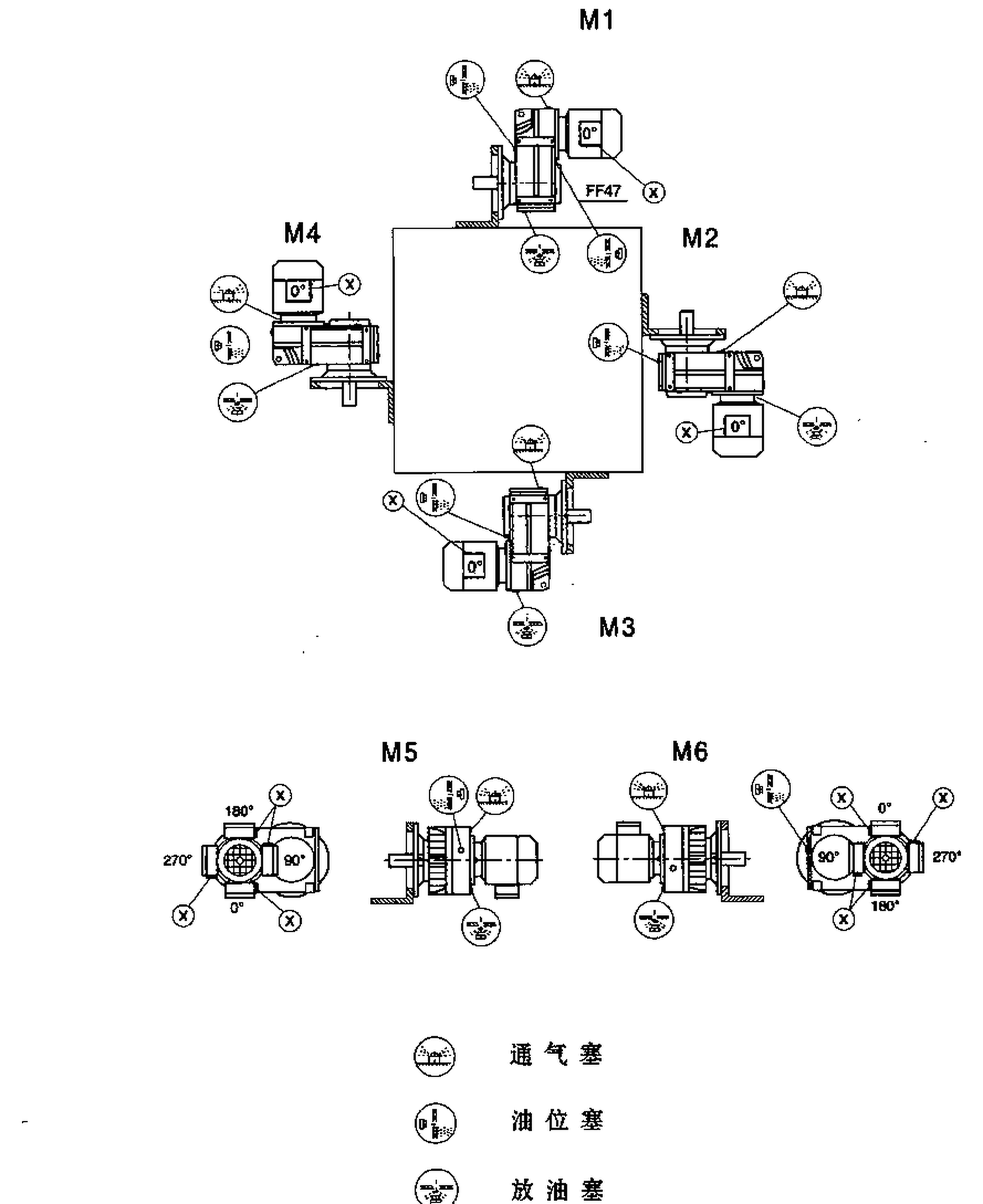
Obtain the exact unit oil quantity and manufacturer-approved lubricant; sign off only for a documented mounting position with complete oil access; an otherwise acceptable compact layout may fail thermal validation.
Plan assembly and disassembly order
A hollow-shaft drive needs a controlled installation method rather than improvised hammering; the machine shaft may need a puller thread or extraction plate after years in operation.
Forcing a gearbox off a corroded shaft can damage the driven machine; record fit-up tools, retaining components and permissible assembly force.
Reserve the axial space and lifting points required by the procedure; the OEM should demonstrate a practical service-removal route before build release; assembly convenience without a removal strategy creates preventable downtime.
Illustrative engineering scenario: A tight conveyor or packaging machine bay
A packaging-line builder wants to move the gearmotor away from a busy loading aisle. The existing inline motor projects into the guard opening. An F-family parallel-shaft layout appears to solve the clearance problem by placing the motor alongside the conveyor. Before adopting it, the engineer marks the conveyor shaft centerline as fixed and overlays two gearbox envelopes: one for a solid output with coupling and another for a hollow output mounted directly on the conveyor shaft. The second layout reduces axial package length, but it also changes how the machine shaft, gearbox housing and frame carry force.
The drawing shows the hollow bore, key engagement, shaft shoulder and a reaction arm. During forward production, the torque arm reacts the housing tendency to rotate; during reverse clearing, the reaction changes direction. Its attachment should allow the movement required by the maker's installation instructions without becoming an extra rigid shaft support. An independent bearing arrangement for the driven roller may still be necessary. When product load creates a sideways force on a sprocket or pulley, the allowable external force must be obtained for the selected unit at the actual lever arm. Nominal transmitted torque cannot answer that question.
Maintenance reviews the installation as a sequence of physical movements. Can a technician get a tool onto the oil plug? Can an output seal be accessed without cutting the conveyor frame? Is there sufficient room to withdraw the gearbox along the shaft if the fit becomes tight after years of service? These checks may reveal that the motor has been moved away from the aisle but the gearbox cannot be repaired in place. A compact layout is successful only when the structural load path, lubrication condition and reasonable future disassembly are all included in the accepted assembly design.
Five-stage review for a tight conveyor or packaging machine bay
-
Use the axis offset deliberatelyDimension the input and output centerlines in a common coordinate system. Approve the arrangement with an interference-free three-dimensional envelope.
-
Check the hollow shaft engagementCompare the F-series hollow-output drawing with the machine shaft manufacturing drawing. A loose or short engagement can cause fretting before the gearbox reaches its rated torque.
-
Compare foot and flange alternativesCheck mounting plate stiffness and specified register tolerance. The selected mount should keep alignment within equipment-approved limits.
-
Build the seal-removal clearanceReserve a tool corridor and safe puller access in the assembled layout. A packaging-only fit check is incomplete for a service-intensive production line.
-
Plan assembly and disassembly orderRecord fit-up tools, retaining components and permissible assembly force. The OEM should demonstrate a practical service-removal route before build release.
Engineering comparison matrix: F series parallel shaft helical gearbox
| Engineering question | Evidence to collect | Review decision |
|---|---|---|
| Use the axis offset deliberately | Capture the actual motor fan clearance and gearbox support reach. | Approve the arrangement with an interference-free three-dimensional envelope. |
| Check the hollow shaft engagement | Compare the F-series hollow-output drawing with the machine shaft manufacturing drawing. | Mating fit and torque transmission should be verified for the ordered variant. |
| Design the torque reaction restraint | Measure the intended reaction attachment location on the supporting frame. | Approve a restrained but non-overconstrained layout against the supplier installation notes. |
| Compare foot and flange alternatives | Include support reaction diagrams and the fastening layout for the actual assembly. | The selected mount should keep alignment within equipment-approved limits. |
| Inspect radial output loads | Request permissible radial force at the actual output speed and force location. | Approval should identify bearing life basis and any external support required. |
| Build the seal-removal clearance | Reserve a tool corridor and safe puller access in the assembled layout. | Maintainability acceptance should be documented at the initial design review. |
Frequently Asked Questions
Does a hollow-output parallel gearbox support an entire conveyor shaft?
What is the function of the F-series torque arm?
Can a parallel-shaft option improve maintenance access?
What belongs on the output-interface drawing?
What makes a final review credible for a tight conveyor or packaging machine bay?
A gearmotor rotated relative to its approved position may feed bearings differently. When comparing actual mounting geometry, use the F-series compact parallel shafts configuration options. Obtain the exact unit oil quantity and manufacturer-approved lubricant.
Record fit-up tools, retaining components and permissible assembly force. For an engineering quotation that records the open conditions, contact the technical team about F-series compact parallel shafts. The OEM should demonstrate a practical service-removal route before build release.
Engineering sources for F-Series Parallel Shaft Helical Gearbox for Compact Machinery
For the f-series parallel shaft helical gearbox for compact machinery workflow, consult these reference documents alongside the actual model installation manual:
- F-Series Parallel Shaft Helical Gearbox for Compact Machinery: SEW-EURODRIVE, Dimension sheet information (analysis).
- F-Series Parallel Shaft Helical Gearbox for Compact Machinery: SEW-EURODRIVE, Change of mounting position (interface review).
- F-Series Parallel Shaft Helical Gearbox for Compact Machinery: SKF, Bearing App documentation (acceptance checks).