
Static load holding, controlled deceleration and emergency safety performance are different requirements. A static brake rating cannot alone certify an emergency stop. Refer to the brake motor load holding guidance. Record controlled, emergency and power-loss use cases. Verify required motor-side holding torque with the correct load direction.
Identify where the brake acts
Check gearbox transient loads
Separate hoist authorization
Clarify what the brake must do
A brake may hold a stopped load, control a service stop or perform a safety-related function; these duties require different torque, energy and reliability evidence.
A static brake rating cannot alone certify an emergency stop; describe stop categories and load-holding requirements.
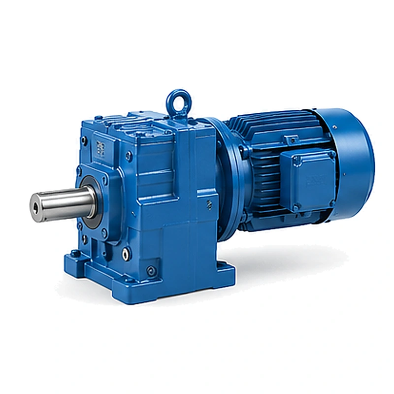
Record controlled, emergency and power-loss use cases; specify a brake with ratings suitable for every assigned function; a brake may be adequate for parking but not repeated high-energy stops.
Identify where the brake acts
A motor-shaft brake sees torque transformed through the reducer ratio and the drivetrain losses; a drum or belt load is not directly equal to the brake torque at the motor.
Ignoring brake location can produce a large sizing error; draw the torque path from load through gearbox to brake.
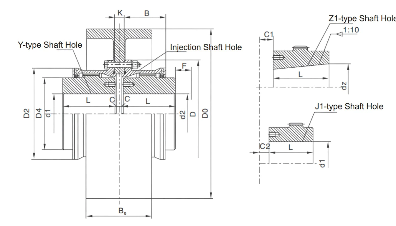
Calculate reflected loading using relevant ratio and efficiency assumptions; verify required motor-side holding torque with the correct load direction; a convenient nominal ratio is not a complete holding calculation.
Estimate kinetic and potential energy
An elevated load carries potential energy and a rotating load carries kinetic energy; a brake stopping moving equipment absorbs energy that must be managed as heat.
Sizing only for static torque ignores repeated stopping duty; collect moving mass, height change, inertia and approach speed.
Estimate brake energy for the most demanding credible event; check brake thermal duty and stopping performance; a brake may hold a parked mechanism yet overheat during cycling.
Define electrical fail behavior
Spring-applied brakes may engage when power is removed but system wiring and control affect the result; a drive may lose power while torque is still acting on a suspended process component.
Control behavior is part of the safety function, not merely a wiring note; map energization, brake release and fail-state sequences.
Document brake power supply and relevant interlocks; validate behavior against machine-level risk requirements; an unspecified power-failure state can lead to uncontrolled motion.
Check gearbox transient loads
Braking shock passes through gear teeth and shafts, potentially reversing torque direction; a strong brake can impose a sharper peak than normal process operation.
Increasing brake torque does not automatically improve gearbox suitability; calculate deceleration profile and drive train peak reactions.
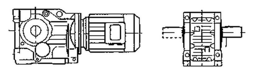
Request permitted geartrain shock and reversing duty for the exact unit; coordinate brake choice with gearbox peak capacity; the strongest brake is not always the safest drive arrangement.
A strong brake can impose a sharper peak than normal process operation. Increasing brake torque does not automatically improve gearbox suitability. Examine the brake motor load holding layout example. Request permitted geartrain shock and reversing duty for the exact unit. Coordinate brake choice with gearbox peak capacity.
Control brake release timing
A motor may need time to build torque before a loaded brake opens; if release is early, the machine can move briefly in the wrong direction.
Poorly tuned sequencing can damage equipment even with correctly sized parts; establish expected motor torque at the release command.
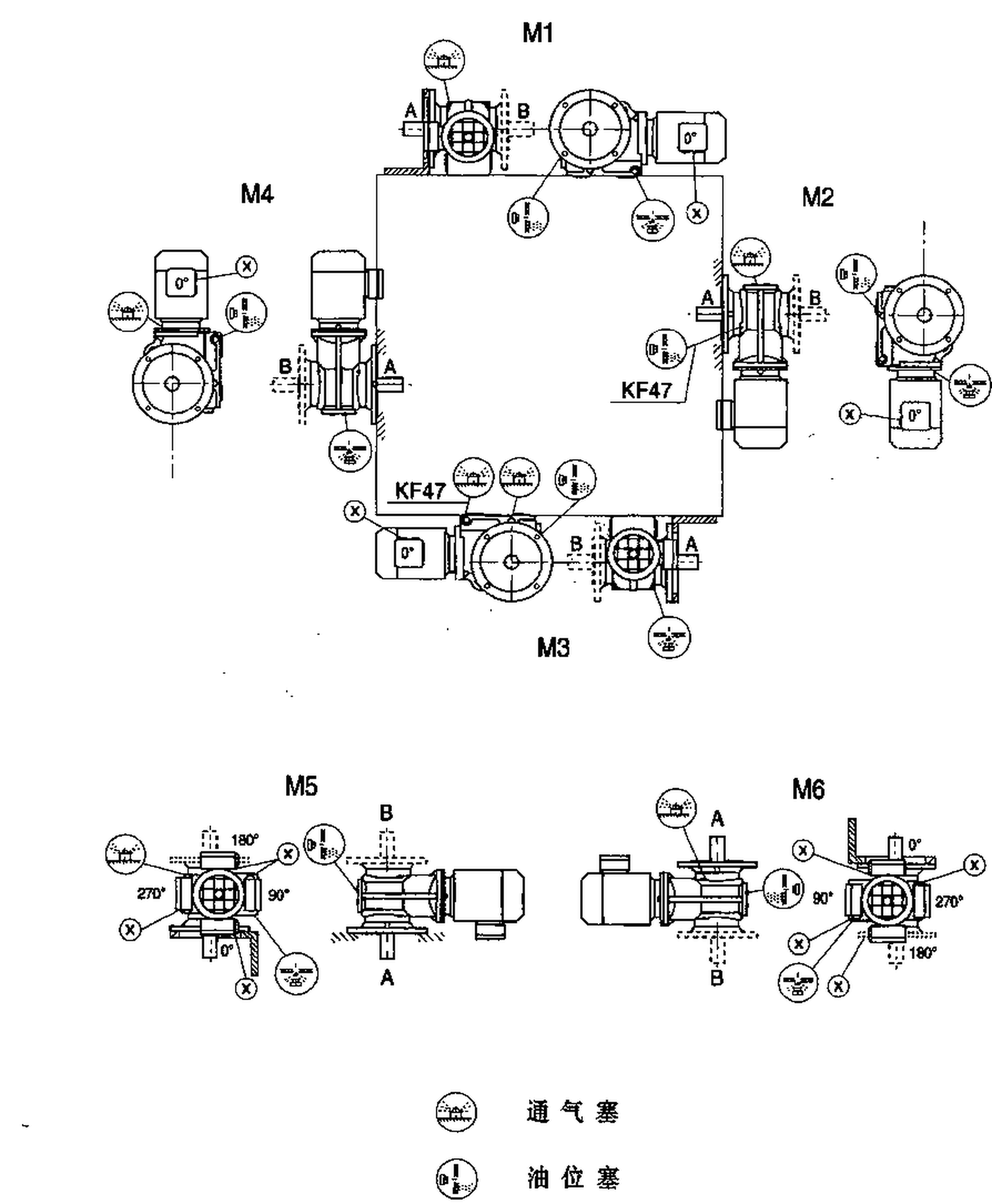
Test interlocks, current and brake response with controlled load; approve release timing under credible machine states; brake design and controller tuning cannot be assessed independently.
Inspect wear and stopping response
Friction surfaces change over operating life and may require service adjustments; brake response and release clearance can drift after repeated cycling.
A once-valid calculation does not eliminate inspection needs; read supplier maintenance and wear-limit instructions.
Record actual air gap, stopping time and operating cycle count if applicable; keep service criteria and functional tests in the maintenance plan; ignoring wear mechanisms can erode an originally adequate safety margin.
Separate hoist authorization
Lifting people or suspended loads introduces strict equipment-level safety obligations; a general industrial gearmotor may not be approved for the complete hoisting assembly.
Treating a brake motor as a compliant lifting drive without evidence is dangerous; identify applicable regulations, crane class and responsible qualified assessor.
Obtain system-specific certifications and inspection provisions where necessary; release lifting duty only following professional engineering sign-off; component-level data never replaces documented hoist safety validation.
Illustrative engineering scenario: A motor-driven machine that must stop or hold a mechanically loaded axis
A conveyor that sometimes stops with material on an incline needs a controlled stopping and holding arrangement. The motor is installed through a helical gearbox, and the brake is mounted on the high-speed motor shaft. A static holding calculation starts by defining the belt load and the output-shaft torque it creates. The ratio transforms this torque back to the brake location, but the calculation also has to use appropriate loss assumptions and the actual direction of power flow. The drive engineer separately considers what happens when the belt is moving and the brake is asked to stop it. Energy absorption, deceleration time and torque peaks are not described by a static holding rating alone.
The control designer maps three scenarios. In normal operation, the drive decelerates before the brake secures the stopped machine. During a power failure, the brake and electrical system must reach a defined safe condition. During maintenance, personnel may need an authorized brake release that prevents unexpected movement. The correct strategy depends on the machinery risk assessment. A normal spring-applied brake may provide an appropriate element, but its presence does not certify the entire system for lifting or guarding functions. If the load is suspended, the requirements can be substantially more demanding, and qualified engineering sign-off is required.
The team then checks the reducer itself. Sudden brake engagement can generate shock through shafts and gearing; a larger nominal brake torque is not automatically a better solution. Braking direction and transient gear capacities must be reconciled with stopping performance. At commissioning, the technician tests the approved sequence with instrumentation and controlled loads, rather than performing an improvised high-energy emergency stop as a casual demonstration. The records include brake location, actual model, wear limits, power-loss behavior and inspection intervals. A satisfactory result shows that the whole motion-control and holding system operates as designed, not merely that the motor stops when its supply is removed.
Brake wear introduces a separate maintenance obligation. A static holding test on a new component does not guarantee the same response after many cycles. The equipment team should know the permitted friction wear, adjustment checks and functional test intervals specified by the brake manufacturer. For equipment that can release stored energy, tests must be conducted under a written machine safety procedure. Unverified performance after a hardware change should remain a commissioning exception until the responsible assessor accepts the results.
Five-stage review for a motor-driven machine that must stop or hold a mechanically loaded axis
-
Clarify what the brake must doDescribe stop categories and load-holding requirements. Specify a brake with ratings suitable for every assigned function.
-
Identify where the brake actsCalculate reflected loading using relevant ratio and efficiency assumptions. A convenient nominal ratio is not a complete holding calculation.
-
Define electrical fail behaviorMap energization, brake release and fail-state sequences. Validate behavior against machine-level risk requirements.
-
Control brake release timingTest interlocks, current and brake response with controlled load. Brake design and controller tuning cannot be assessed independently.
-
Separate hoist authorizationIdentify applicable regulations, crane class and responsible qualified assessor. Release lifting duty only following professional engineering sign-off.
Engineering comparison matrix: helical gearbox brake motor holding torque
| Engineering question | Evidence to collect | Review decision |
|---|---|---|
| Clarify what the brake must do | Record controlled, emergency and power-loss use cases. | Specify a brake with ratings suitable for every assigned function. |
| Identify where the brake acts | Calculate reflected loading using relevant ratio and efficiency assumptions. | Verify required motor-side holding torque with the correct load direction. |
| Estimate kinetic and potential energy | Estimate brake energy for the most demanding credible event. | Check brake thermal duty and stopping performance. |
| Define electrical fail behavior | Document brake power supply and relevant interlocks. | Validate behavior against machine-level risk requirements. |
| Check gearbox transient loads | Request permitted geartrain shock and reversing duty for the exact unit. | Coordinate brake choice with gearbox peak capacity. |
| Control brake release timing | Test interlocks, current and brake response with controlled load. | Approve release timing under credible machine states. |
Frequently Asked Questions
Is the motor-side holding brake torque the same as drum torque?
Why must stopping energy be checked as well as static torque?
Does a spring-applied motor brake make a hoist automatically safe?
Could selecting a stronger brake damage the reducer?
What makes a final review credible for a motor-driven machine that must stop or hold a mechanically loaded axis?
Brake response and release clearance can drift after repeated cycling. When comparing actual mounting geometry, use the brake motor load holding configuration options. Record actual air gap, stopping time and operating cycle count if applicable.
Identify applicable regulations, crane class and responsible qualified assessor. For an engineering quotation that records the open conditions, contact the technical team about brake motor load holding. Release lifting duty only following professional engineering sign-off.
Engineering sources for Brake Motors and Helical Gearboxes for Holding Loads
For the brake motors and helical gearboxes for holding loads workflow, consult these reference documents alongside the actual model installation manual:
- Brake Motors and Helical Gearboxes for Holding Loads: SEW-EURODRIVE, Lifting applications (analysis).
- Brake Motors and Helical Gearboxes for Holding Loads: SEW-EURODRIVE, Basic calculation process (interface review).
- Brake Motors and Helical Gearboxes for Holding Loads: SEW-EURODRIVE, Application-specific service factor (acceptance checks).