
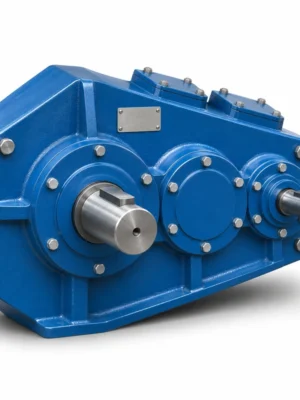
Audible noise is evidence to investigate, but fault location depends on whether the sound tracks speed, torque or the machine structure.
The EP-DQJ/DQJD Point-Line Meshing Crane Gear Reducer family covers reducers that use a point-line meshing gear arrangement while offering distinct ways of supporting the housing on the machine. DQJ identifies the three-point supported configuration, while the DQJD designation is used for a foot-mounted construction. The mounting difference directly affects the layout of the crane drive, the position of bearing reactions and the measurements required from an existing reducer. The starting decision is therefore the mechanical installation concept, followed by stage configuration, nominal center distance, reduction ratio, assembly position and output shaft design.
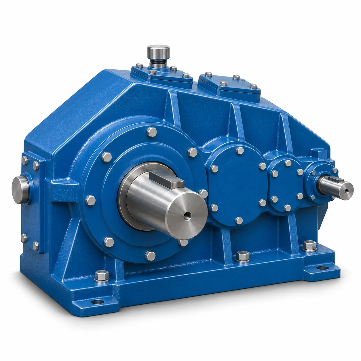
Support system
DQJ uses a three-point support construction; DQJD is identified as a foot-mounted design.
Reduction construction
R, S and RS designate two-stage, three-stage and combined construction types.
Output interface
P, H and C designate alternative output shaft-end types; each requires its own matching geometry.
DQJ vs DQJD: How the Gearbox Is Supported
For an installation with a three-point support structure, mounting accuracy depends on how the existing supports are located around the main casing and output-side connection. The support geometry is not a set of independent flat feet. A foot-mounted reducer instead transfers the equipment loads into a base or seating surface through a defined mounting pattern. Neither format is automatically superior: each is appropriate only when the surrounding crane structure, housing stiffness and available shaft interfaces are compatible with the proposed arrangement.
| Decision | Three-point support DQJ | Foot-mounted DQJD |
|---|---|---|
| Two-stage form | DQJR | DQJRD |
| Three-stage form | DQJS | DQJSD |
| Combined two-/three-stage form | DQJRS | DQJRSD |
| Primary support | Three-point arrangement | Foundation/foot arrangement |
| Orientation information | W horizontal and L vertical arrangements are illustrated | Foot-mounted configuration requires a drawing-specific check |
| Output options | P / H / C shaft-end choices | P / H / C shaft-end choices |
During replacement work, a two-stage DQJR configuration should not be compared with a three-stage DQJSD merely because their gear housings seem to occupy a similar space. The gear-train stages and the mounting method are separate aspects of the model code. The complete designation combines both, so purchasing should request a full nameplate string or a drawing rather than a shortened family name when assessing fit.
Decode the DQJ/DQJD Model Designation
The model designation diagram organizes the order reference from construction type through nominal center distance, reduction ratio, assembly form, shaft-end type and mounting orientation. Missing characters can change how the reducer sits in the equipment. A code such as DQJR560-20VICW identifies the three-point two-stage construction, 560 mm nominal output-stage center distance, 20:1 nominal ratio, specified assembly VI, C-type output and horizontal W orientation. Another illustrated format, DQJSD400-50IIIP, identifies a foot-mounted three-stage form with 400 mm nominal center distance, 50:1 ratio, assembly III and P output. These are code-reading examples, not current stock confirmations.
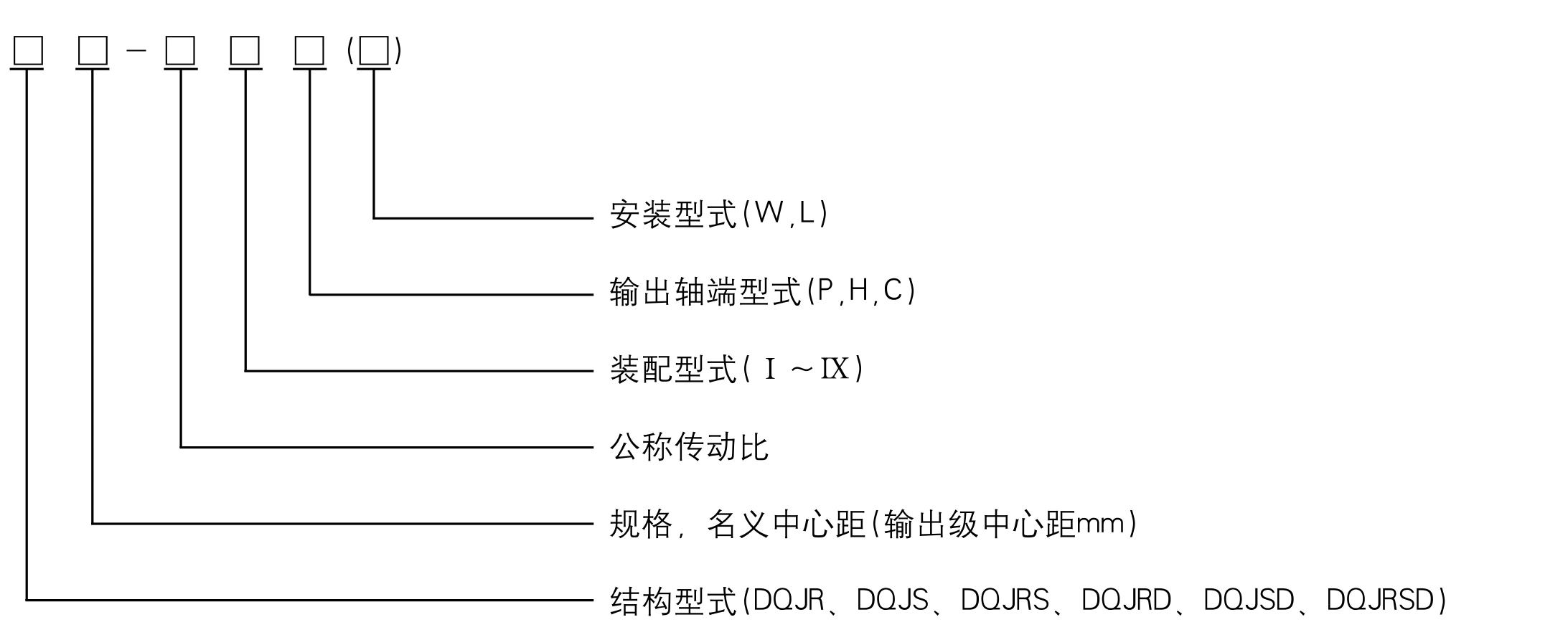
- Structure identifier: confirm DQJR, DQJS, DQJRS, DQJRD, DQJSD or DQJRSD without substituting a similar-looking code.
- Center-distance entry: match the nominal center distance against the model and actual installation drawing.
- Ratio and assembly: specify the nominal ratio and the assembly position separately; neither value determines the other.
- Shaft-end letters: select P, H or C only after reviewing the adjacent mechanical component and the relevant fit information.
- Mounting code: mark horizontal or vertical where this arrangement is supported, and verify lubrication and access for the final position.
Assembly Positions III to IX
Assembly positions show how the input and output interfaces are oriented relative to the housing. The identifier III through IX belongs in the order designation, but it is not a substitute for a dimensioned view. Before specifying a position, stand at the same reference side of the old gearbox as indicated in the technical drawing and mark which shaft connects to the motor. Misreading an assembly sketch from the opposite side can place the intended coupling on the wrong side of the casing and create an installation conflict even when shaft sizes match.

Horizontal and Vertical Installation Orientation
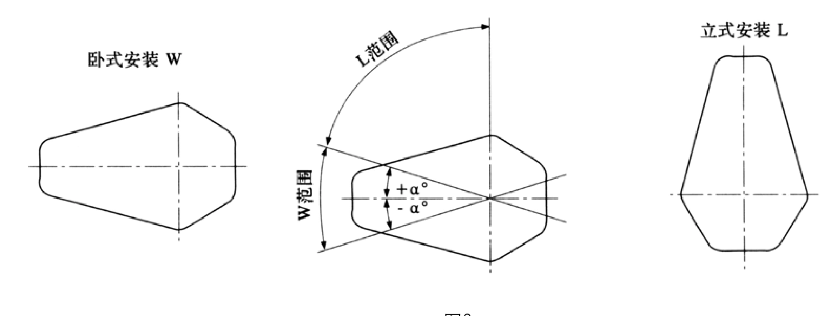
The three-point support diagrams show a horizontal W position and a vertical L position, together with a limited tilt range for the W arrangement. These illustrations are relevant to the DQJ-style supported housing. Do not read them as proof that every DQJD foot-mounted gearbox can run in every pictured attitude. Lubrication, bearing loading and support details should be checked for the exact built configuration, particularly where the input coupling is elevated above a working platform or the output shaft is partially enclosed by the surrounding equipment.
Three-Point Support: Locating the Gearbox Without Distortion
The detailed support drawing identifies contact and restraint features at positions X, Y and Z. These are installation interfaces, not ornamental cover details. An engineer should understand the nominal bearing-seat arrangement and the clearance or fit implied by each section before specifying a support plate or modifying an existing structure. Where a reducer is mounted to a welded frame, the position of the three support reactions must be established from measured datums. Forcing the housing into place with bolts can introduce stress into bearing seats and distort alignment.
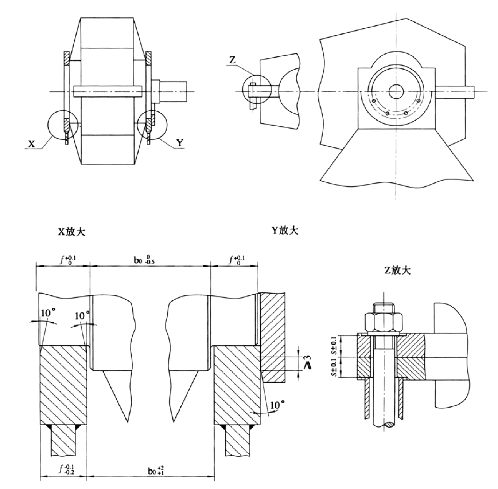
When the working mechanism is being rebuilt, document the load path from the driven shaft through the casing into the supporting steelwork. The three-point arrangement can reduce the dependence on a full flat seating surface, but it does not remove the need to control location, engagement and fastener restraint. For an alternative mounting concept, the EP-QY3S three-support crane gearbox offers another series for comparison, whereas the EP-QY3D foot-mounted gearbox illustrates how a conventional base interface changes the installation decision. These are comparison links, not declarations of interchangeability.
P, H and C Output Shaft Interfaces
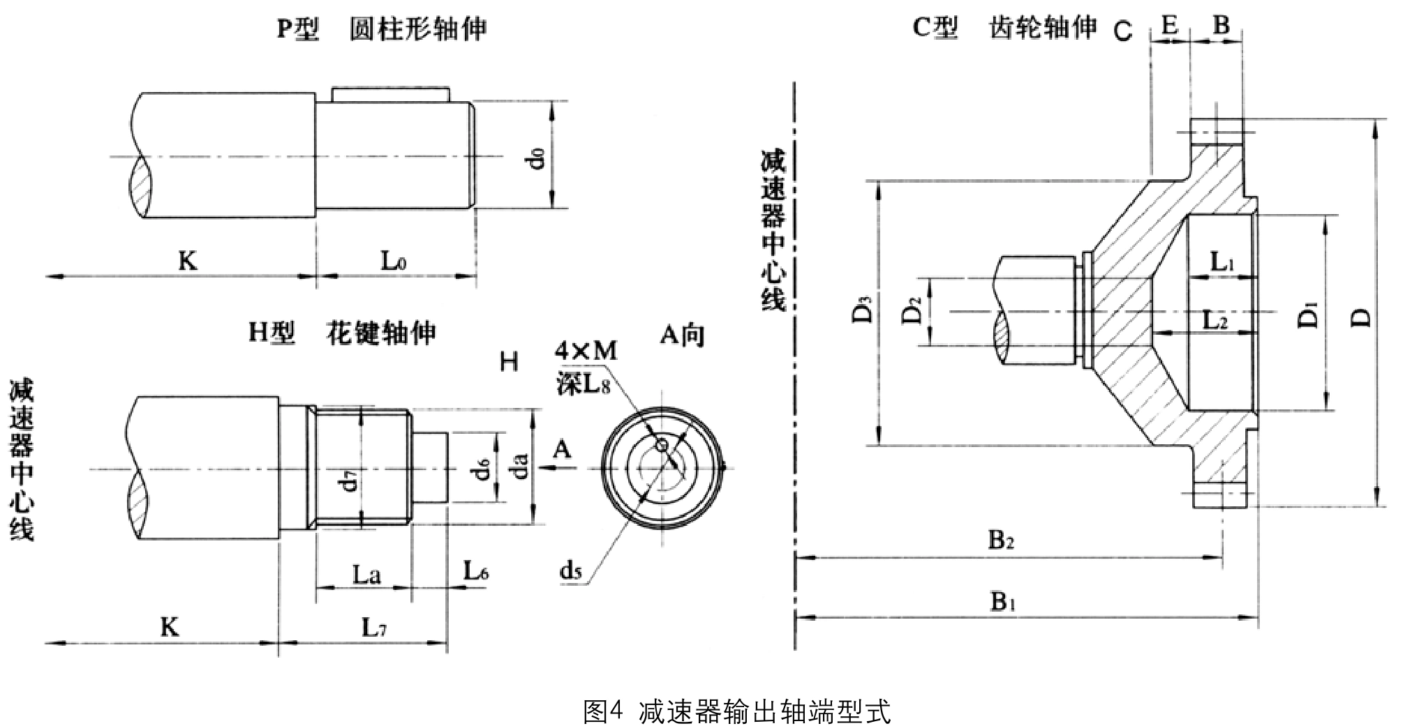
The P configuration is the cylindrical output-shaft form, H is the involute spline output, and C is the involute gear-shaft output. The C arrangement has a different mating requirement from a plain shaft and key: tooth module, tooth count, pressure angle where applicable and axial engagement must be established from the mechanical drawing. The spline option similarly requires correct tooth geometry and the relevant fit. The chosen shaft interface is an engineering decision, not a decorative version of the same external housing.
P and H Shaft-End Dimension Schedule
The dimensional schedule below organizes the nominal center distance with the P-type cylindrical shaft and H-type involute-spline variables shown in the shaft-end drawing. A plain shaft size and a spline designation cannot be interchanged; each table column applies to the geometry shown above. If a dimension cell has alternative values, the required variant should be stated on the drawing and confirmed before the mating component is manufactured.
| Nominal center distance | k | P d0 | P L0 | H m x z | H da (H11) | H La | H d5 | H M | H d6 (k6) | H L6 | H d7 (k6) | H L7 | H L8 |
|---|---|---|---|---|---|---|---|---|---|---|---|---|---|
| 140 | 130 | 48 | 82 | 3x15 | 48 | 35 | 25 | 6 | 40 | 23 | 50 | 78 | 12 |
| 170 | 140 | 55 | 82 | 3x18 | 57 | 35 | 30 | 6 | 50 | 27 | 60 | 82 | 12 |
| 200 | 195 | 65 | 105 | 3x22 | 69 | 40 | 40 | 8 | 60 | 30 | 70 | 90 | 16 |
| 236 | 225 | 80 | 130 | 3x27 | 84 | 45 | 50 | 8 | 70 | 30 | 85 | 95 | 16 |
| 280 | 250 | 90 | 130 | 5x18 | 95 | 55 | 60 | 8 | 80 | 35 | 100 | 125 | 16 |
| 335 | 280 | 110 | 165 | 5x22 | 115 | 60 | 70 | 10 | 100 | 40 | 120 | 135 | 20 |
| 400 | 340 | 130 (140) | 200 | 5x26 | 135 | 75 | 90 | 10 | 120 | 45 | 140 | 155 | 20 |
| 450 | 365 | 150 | 200 | 5x30 | 155 | 80 | 100 | 12 | 140 | 50 | 160 | 165 | 25 |
| 500 | 410 | 170 (180) | 240 | 5x34 | 175 | 90 | 120 | 12 | 160 | 55 | 180 | 180 | 25 |
| 560 | 445 | 190 (200) | 280 | 5x38 | 195 | 100 | 140 | 12 | 180 | 55 | 200 | 190 | 25 |
| 630 | 495 | 220 | 280 | 8x26 | 216 | 110 | 160 | 12 | 190 | 60 | 222 | 205 | 25 |
| 710 | 565 | 250 (260) | 330 | 8x30 | 248 | 125 | 180 | 16 | 220 | 60 | 254 | 220 | 32 |
| 800 | 615 | 280 | 380 | 8x34 | 280 | 140 | 200 | 16 | 250 | 60 | 286 | 235 | 32 |
| 900 | 670 | 320 | 380 | 8x38 | 312 | 155 | 220 | 20 | 280 | 70 | 318 | 260 | 40 |
| 1000 | 740 | 360 | 450 | 8x44 | 360 | 175 | 250 | 20 | 320 | 75 | 366 | 285 | 40 |
Parentheses indicate alternative nominal P shaft dimensions as shown in the reference table; select only the specified variant for the supplied unit.
C-Type Geared Output Dimension Schedule
The C output uses a toothed extension rather than a plain cylindrical end. The detailed schedule begins at a nominal center distance of 236 mm, and its entries must be paired with the C-type outline sketch, not with the P or H drawing. The toothed-output design can alter the way backlash, mesh alignment and external support are managed. Request the mating-gear drawing where the reducer is intended to drive a gear or drum-mounted member directly.
| Center distance | m x z | D | D1 (H7) | D2 | D3 | B1 | B2 | B | E | L1 | L2 |
|---|---|---|---|---|---|---|---|---|---|---|---|
| 236 | 3x56 | 174 | 90 | 40 | 135 | 279.5 | 253 | 25 | 25 | 45 | 60 |
| 280 | 4x56 | 232 | 120 | 40 | 170 | 302.5 | 271 | 35 | 25 | 50 | 75 |
| 335 | 4x56 | 232 | 120 | 40 | 170 | 339.5 | 308 | 35 | 25 | 50 | 75 |
| 400 | 6x56 | 348 | 170 | 45 | 260 | 402 | 370 | 40 | 32 | 76 | 100 |
| 450 | 6x56 | 348 | 170 | 45 | 260 | 429 | 397 | 40 | 32 | 76 | 100 |
| 500 | 8x54 | 448 | 200 | 105 | 260 | 482 | 442 | 50 | 32 | 78 | 100 |
| 560 | 10x48 | 500 | 200 | 105 | 280 | 570 | 505 | 60 | 35 | 78 | 110 |
| 630 | 10x54 | 560 | 250 | 140 | 380 | 620 | 550 | 65 | 40 | 80 | 120 |
| 710 | 12x48 | 600 | 270 | 150 | 420 | 700 | 620 | 75 | 45 | 88 | 130 |
| 800 | 12x54 | 672 | 290 | 170 | 480 | 776 | 696 | 75 | 45 | 95 | 130 |
| 900 | 12x58 | 720 | 310 | 180 | 560 | 850 | 770 | 85 | 60 | 105 | 140 |
| 1000 | 12x64 | 792 | 380 | 230 | 620 | 970 | 895 | 100 | 80 | 140 | 180 |
For C-type output, check tooth geometry and mating arrangement; nominal values alone do not establish complete mesh compatibility.
Operating Conditions to Confirm Before Selection
The reference operating envelope discusses circumferential gear speed, high-speed-shaft rotation, ambient temperature and reversible operation. These values should be used as questions for engineering qualification rather than as an unconditional rating for a modern supplied gearbox. Duty classification, actual torque, thermal behavior and lubrication depend on the complete model and installation. For crane hoisting duty, control of suspended loads and braking must also be assessed at system level rather than assumed from reducer construction.
| Engineering item | Reference figure or condition | What to confirm |
|---|---|---|
| Gear peripheral speed | At most 16 m/s | Actual tooth speed for selected ratio and input |
| High-speed-shaft speed | At most 1,500 r/min | Motor rated speed and overspeed events |
| Ambient temperature | -40 to +50 C | Lubricant, seals and thermal suitability |
| Direction of rotation | Forward and reverse operation | Start-stop cycle and reversing torque |
Replacement and Ordering Checklist for DQJ/DQJD
A useful quotation request combines the full gearbox code with annotated photographs showing the installed support pattern. The buyer should identify whether the original reducer uses three-point supports or a base, since a dimensionally similar housing may still need a different foundation. Include the drive-side and load-side view, measured center distance, chosen assembly position, shaft-end construction, motor data and the actual operating cycle. If a gearbox is being replaced due to recurring failure, note the observed failure location and any change in machine operation.
- Support geometry: three-point X/Y/Z arrangement or foot-to-foundation hole pattern.
- Connection geometry: P, H or C end, mating shaft or gear drawing, and engagement/retention details.
- Transmission data: input speed, target output speed and nominal ratio.
- Crane duty: load state, reversals, any unusual shock and braking requirements.
- Evidence for matching: drawing, close-up dimension photographs, sample or inspection results when available.
The broader crane gearbox collection can be used to compare other support architectures, but the correct selection follows a verified interface and duty review. Distinct support types should never be treated as interchangeable because their English product names share the word gearbox.
Frequently Asked Questions
The following answers focus on the decisions that typically need to be resolved before an engineer can confirm a suitable crane gearbox configuration.
Specify a DQJ or DQJD Installation
Share the structure code, center distance, output-end type, ratio, assembly position and an installation drawing. Ever Power can review which support form suits the machine and discuss a drawing-specific quotation.