
Audible noise is evidence to investigate, but fault location depends on whether the sound tracks speed, torque or the machine structure.
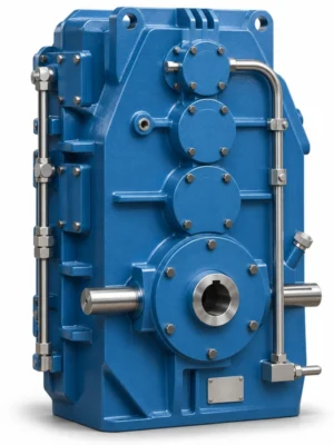
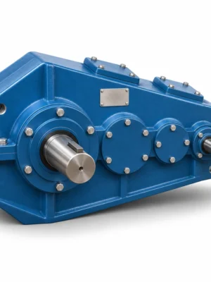
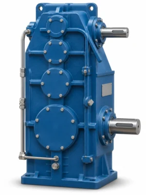
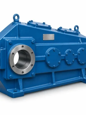
EP-QJY2 Two-Stage Hardened Crane Gear Reducer is specified for two-stage ratio efficiency and compactness. The QJY2 crane gear reducer is the two-stage member of a broader hardened-tooth family, making it relevant when the required reduction is moderate and the machinery benefits from a shorter gear train. A buyer should first establish the output speed needed at the driven shaft, then investigate available ratios within the 6.3–20 nominal range. The motor speed, duty factor and allowable output torque are part of the same decision. Selecting a low ratio to maximize travel speed without examining accelerating loads can overload the connected shaft and coupling.
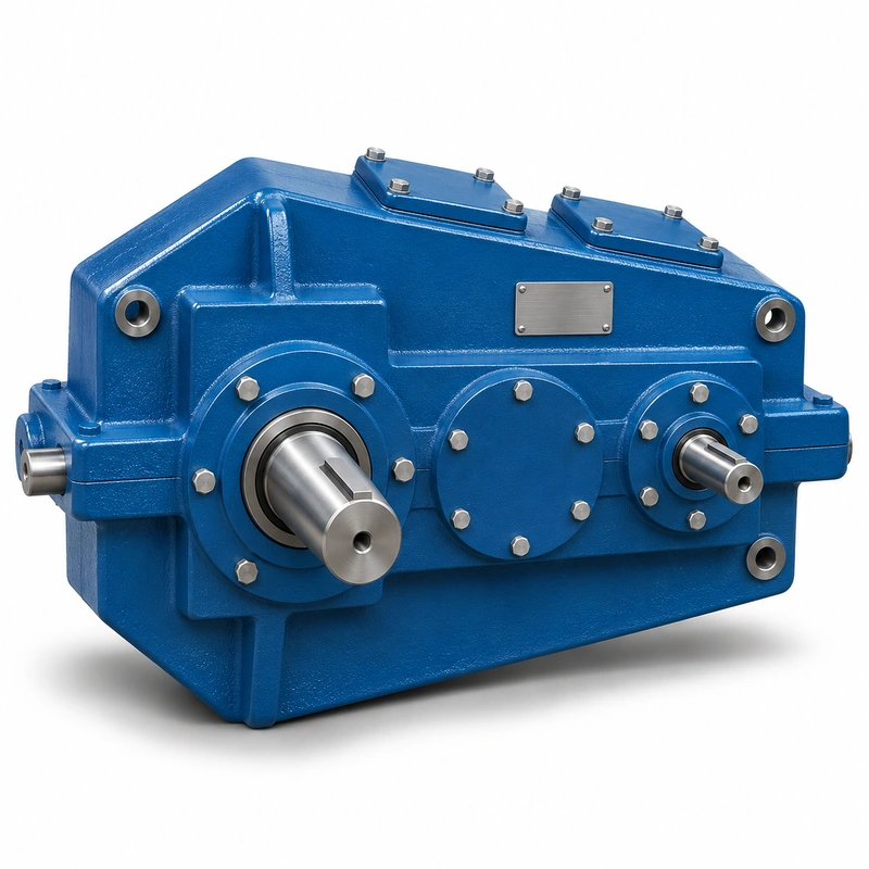
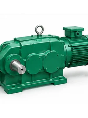
The basic QJY2 designation should not be used as a blanket reference for every foot-mounted or hollow-shaft form of the family. QJYD2 and QJYA2 identify other arrangements. A quotation based only on 'QJY2' leaves uncertain the attachment orientation, output form and machine interface. Give the basic model code together with centre distance and drawings so that the purchase specification is unambiguous.
Mechanical rationale and transmission selection
Reduction calculation
When evaluating a two-stage crane reducer, compare actual input rpm to target output rpm rather than assuming a familiar ratio from another crane. A 6.3 ratio and a 20 ratio impose very different shaft-speed, brake and coupling considerations. If a variable-speed drive is used, identify the normal operating point and the extremes separately.
Model range interpretation
The two-stage family covers nominal centre distances from 140 to 800 mm, but not every configuration is available at every combination. The overall applicable power range in the family overview is not a rating for one gearbox. Select a centre distance, speed and transmission ratio together and require the matching torque schedule in the confirmed drawing or quotation.
Two-stage versus three-stage
A two-stage layout is useful where a three-stage reduction is unnecessary. Adding stages simply to obtain a familiar housing can change efficiency, thermal loading, centreline spacing and enclosure dimensions. Conversely, a two-stage gearbox with the required ratio may still be unsuitable if the output torque or driven speed requires another configuration.
Drawing selection
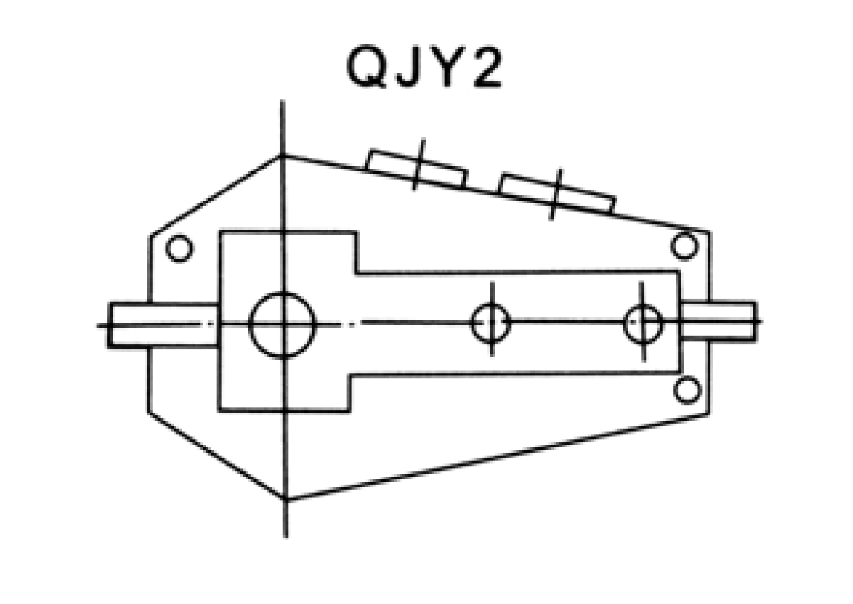
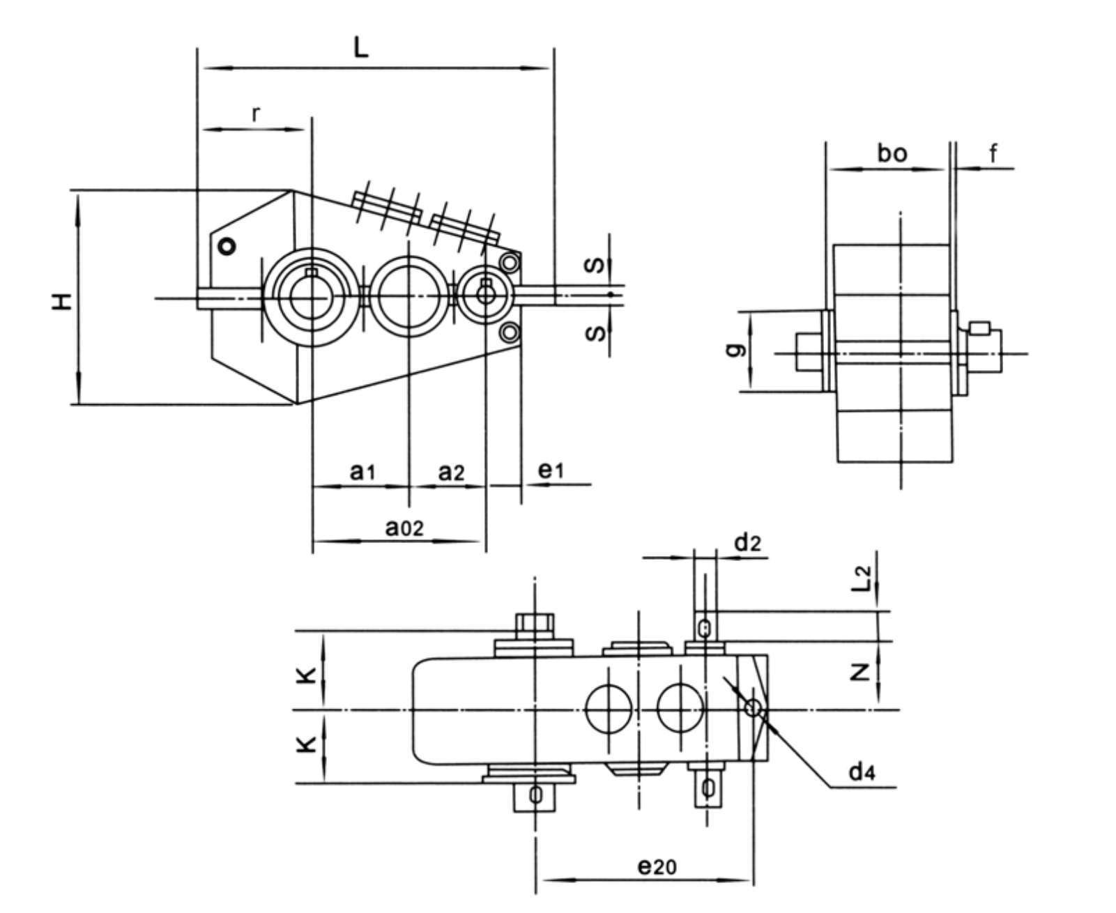
Compare all dimensional views, including the gearbox length, fastening locations, high-speed input, low-speed output and the spatial separation of shafts. A dimension drawing gives geometry, not permission to exceed rated loads. Ensure the mounting scheme chosen for the project matches the sketch and the model code.
Coupling and bearing reaction
With a relatively fast output shaft, coupling balance and alignment become more visible. Record whether the output is coupled directly or carries an overhung pulley, sprocket or gear. The latter can introduce radial and axial forces that require separate bearing checks and cannot be approved by the torque table alone.
Installation validation
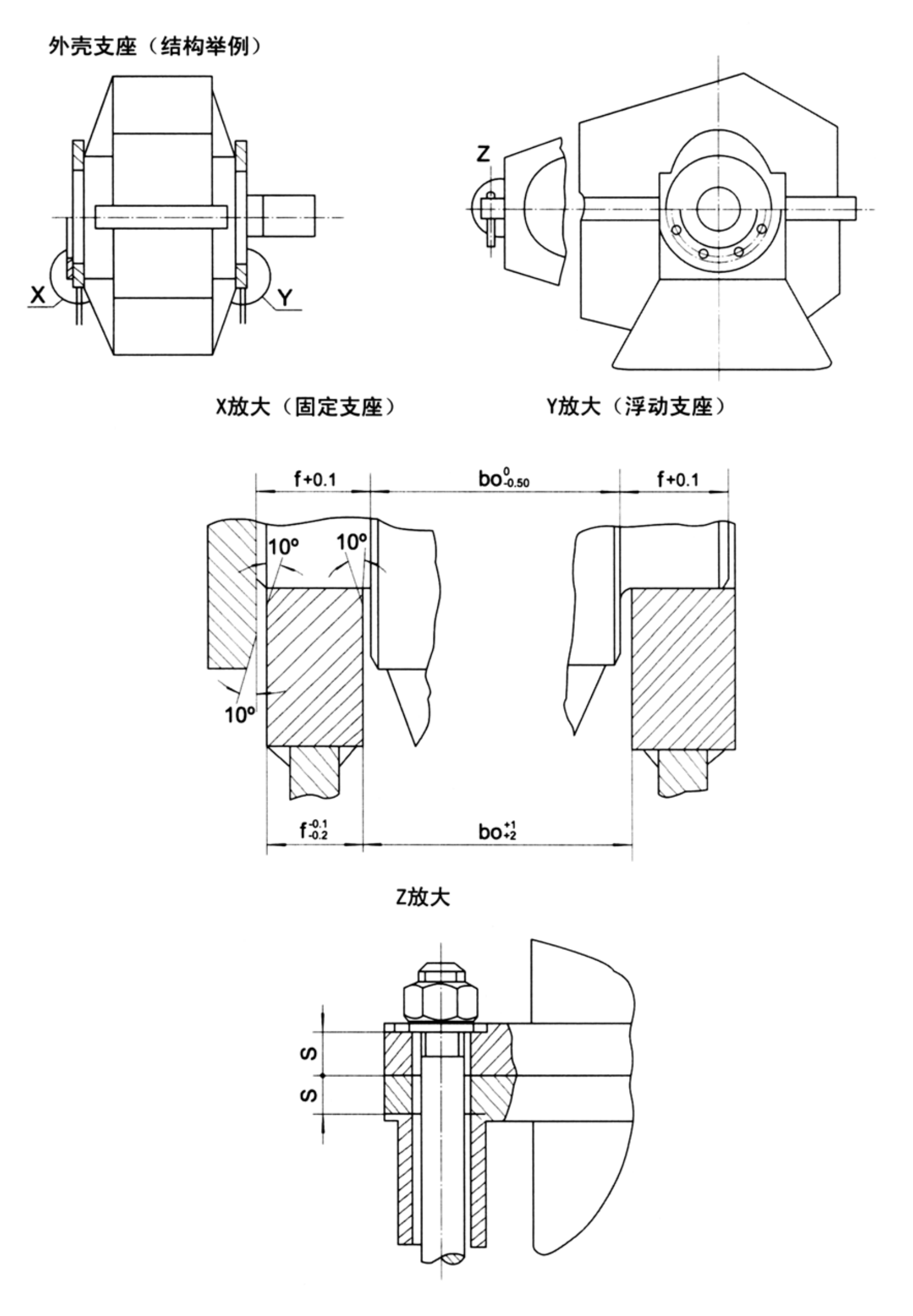
Check foundation rigidity and shaft alignment before first energization. Run the assembly at controlled load, listen for irregular mesh or bearing noise and monitor oil temperature. Repeat checks after an initial service interval in the duty representative of the crane. Confirm that the lubrication configuration suits the mounting position.
Procurement package
For a replacement drive, attach the actual gearbox tag, existing shaft drawings, motor plate, coupling details and duty cycle. For an OEM design, specify the mechanical envelope, permissible mass, output speed and desired mounting direction. Either approach lets the quotation address functional fit rather than only a catalogue ratio.
Matching the reducer to the driven machine
For an EP-QJY2 installation, the main decision concerns two-stage ratio efficiency and compactness. Two-stage efficiency or compactness cannot be quantified without the actual motor, speed and loss assumptions. The best starting point is the actual machine arrangement, the operating load and the requested output speed.
Select
Confirm the true mechanical work point for QJY2 Crane Gear Reducer: input speed, demanded output torque and the dynamic events that govern component loading.
Measure
Use the QJY2 dimensional drawing to validate the installation envelope, shaft interfaces, mounting features and clearances on the actual machine.
Integrate
Match the selected drive with the connected motor, brake, coupling and supporting crane structure. Treat fit and control as one application.
Maintain
Plan access for lubrication, seals, inspection and removal. A compatible gearbox should also be practical to service after the crane is installed.
Selecting a faster travel mechanism
A crane travel unit designed around a moderate 6.3–20 ratio needs to meet wheel-speed targets without overloading a shaft. Provide wheel diameter, moving weight and acceleration rather than guessing from the motor power alone.
Two-stage mechanism examples
- Crane travel transmission with modest reduction demand: describe the working load and mechanical interface before defining the reducer or gearmotor variant.
- Hoist auxiliary drives where the speed schedule fits a two-stage unit: describe the working load and mechanical interface before defining the reducer or gearmotor variant.
- OEM machine design prioritizing a shorter power path: describe the working load and mechanical interface before defining the reducer or gearmotor variant.
QJY2 specification and model identification
QJY2 Crane Gear Reducer selection is defined by the combination of family construction, operating point and machine interfaces. The following data identifies the documented product family; a specific configuration must still be checked against its dimensional drawing and duty schedule.
| Parameter | Series-level reference |
|---|---|
| Gear stages | 2 |
| Nominal transmission ratio | 6.3–20 |
| Family centre-distance range | 140–800 mm |
| Family applicable power span | 8.7–5717 kW in family overview; size and duty specific |
| Typical variant | QJY2 basic layout; QJYD2 and QJYA2 are separate mount/interface variants |
The nominal centre-distance schedule below covers 14 named frame entries. It is a series index, not a statement that every combination of nominal ratio, shaft end and mounting exists at every size.
| Frame reference | Nominal centre distance | Ordering condition |
|---|---|---|
| Nominal centre a1 = 140 mm | 140 mm | Confirm ratio, interface and load rating for the requested version |
| Nominal centre a1 = 170 mm | 170 mm | Confirm ratio, interface and load rating for the requested version |
| Nominal centre a1 = 200 mm | 200 mm | Confirm ratio, interface and load rating for the requested version |
| Nominal centre a1 = 236 mm | 236 mm | Confirm ratio, interface and load rating for the requested version |
| Nominal centre a1 = 280 mm | 280 mm | Confirm ratio, interface and load rating for the requested version |
| Nominal centre a1 = 335 mm | 335 mm | Confirm ratio, interface and load rating for the requested version |
| Nominal centre a1 = 370 mm | 370 mm | Confirm ratio, interface and load rating for the requested version |
| Nominal centre a1 = 400 mm | 400 mm | Confirm ratio, interface and load rating for the requested version |
| Nominal centre a1 = 450 mm | 450 mm | Confirm ratio, interface and load rating for the requested version |
| Nominal centre a1 = 500 mm | 500 mm | Confirm ratio, interface and load rating for the requested version |
| Nominal centre a1 = 560 mm | 560 mm | Confirm ratio, interface and load rating for the requested version |
| Nominal centre a1 = 630 mm | 630 mm | Confirm ratio, interface and load rating for the requested version |
| Nominal centre a1 = 710 mm | 710 mm | Confirm ratio, interface and load rating for the requested version |
| Nominal centre a1 = 800 mm | 800 mm | Confirm ratio, interface and load rating for the requested version |
Information for two-stage gear selection
- 2-stage target nominal ratio: include the appropriate drawing, measured value, operating cycle or connection detail.
- Actual motor rpm and drive-control range: include the appropriate drawing, measured value, operating cycle or connection detail.
- Required high-speed/low-speed shaft centres: include the appropriate drawing, measured value, operating cycle or connection detail.
- Nominal gear centre distance: include the appropriate drawing, measured value, operating cycle or connection detail.
- External shaft radial force: include the appropriate drawing, measured value, operating cycle or connection detail.
- Mounted coupling parameters: include the appropriate drawing, measured value, operating cycle or connection detail.
- Operating hours and starts: include the appropriate drawing, measured value, operating cycle or connection detail.
- Existing drive photograph or drawing: include the appropriate drawing, measured value, operating cycle or connection detail.
Commercial enquiry for the QJY2 series
Ever Power can discuss model identification, interface drawings and practical order quantities for the QJY2 Crane Gear Reducer. Confirmed product configuration, lead time and delivery terms belong in the quotation. Trial and mixed-model requests can be assessed against the total order value.
To compare related drive families, explore the industrial drive product range. The company overview explains the supplier context for engineering and procurement enquiries.
Frequently asked questions about EP-QJY2
How is EP-QJY2 different from EP-QJY3?
QJY2 is the two-stage family in the nominal 6.3–20 range, whereas QJY3 is a three-stage family for higher nominal reductions. The appropriate selection is determined by output torque, speed, interfaces and duty rather than stage count alone.
Is 5717 kW the rating of every QJY2 size?
No. It is the upper end of a broad family-level applicable power span, not an individual gearbox guarantee. Request the operating-point rating for the selected centre distance, input speed and ratio.
Which drawing should accompany a QJY2 purchase order?
Use a dimensioned drawing of the chosen basic QJY2 configuration showing shaft ends, centre distances, mounting features and orientation. A foot-mounted QJYD2 or hollow-shaft QJYA2 image is not a substitute.
Is the purchase quantity fixed for this model for EP-QJY2?
There is no blanket unit count for all configurations: MOQ follows the part type and order value. Trials of 1–5 pieces are possible where practical, while a 1–2-piece small order normally has a higher unit price. Mixed-model orders can be considered from about USD 1,500 in aggregate value. For this product, quote preparation should also address two-stage ratio efficiency and compactness and the requested quantity.
When could an engineered crane reducer be delivered for EP-QJY2?
The schedule depends on the confirmed drawing and production route: standard products typically require 10–25 working days, custom components 20–45 and project-scale equipment 45–120. These are planning ranges, not a promised ship date. Normal trade terms include EXW, FOB, CIF and DAP, with FCA, CFR, CPT, CIP and DDP subject to agreement. Schedule confirmation follows review of the QJY2 interface and duty requirements.
Select the correct two-stage crane reducer
Send the input speed, required output speed, loading and installation drawing to review an EP-QJY2 selection. We can structure a quotation around the real machine interfaces and planned duty.