
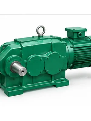
Audible noise is evidence to investigate, but fault location depends on whether the sound tracks speed, torque or the machine structure.
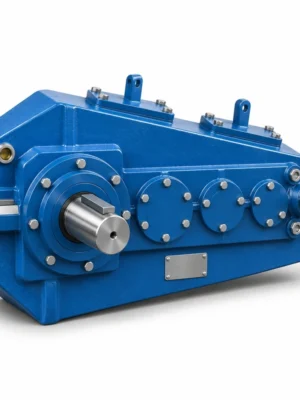
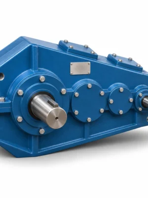
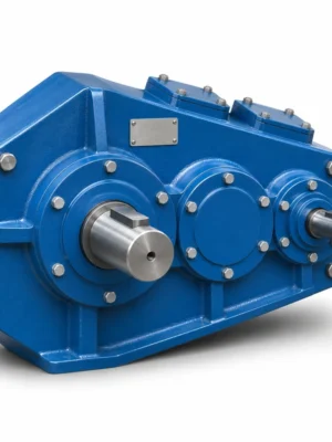
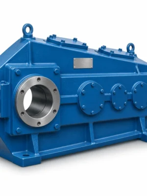
EP-QY3D Foot-Mounted Hardened Crane Gearbox is specified for foundation footprint, shimming and coupling centerline. The QY3D addresses a different mechanical problem from a support-suspended reducer: it places the housing load and torque reaction through a foot-mounted base. A replacement enquiry should therefore focus on the foundation rather than only the nominal centre distance. Measure the base hole pattern, installed height and the space available for coupling removal. If the original reducer was grouted or mounted on a welded stool, its support surfaces can be distorted by years of service. A new gearbox should not be bolted down to an uneven plate in the hope that the casing will pull flat.
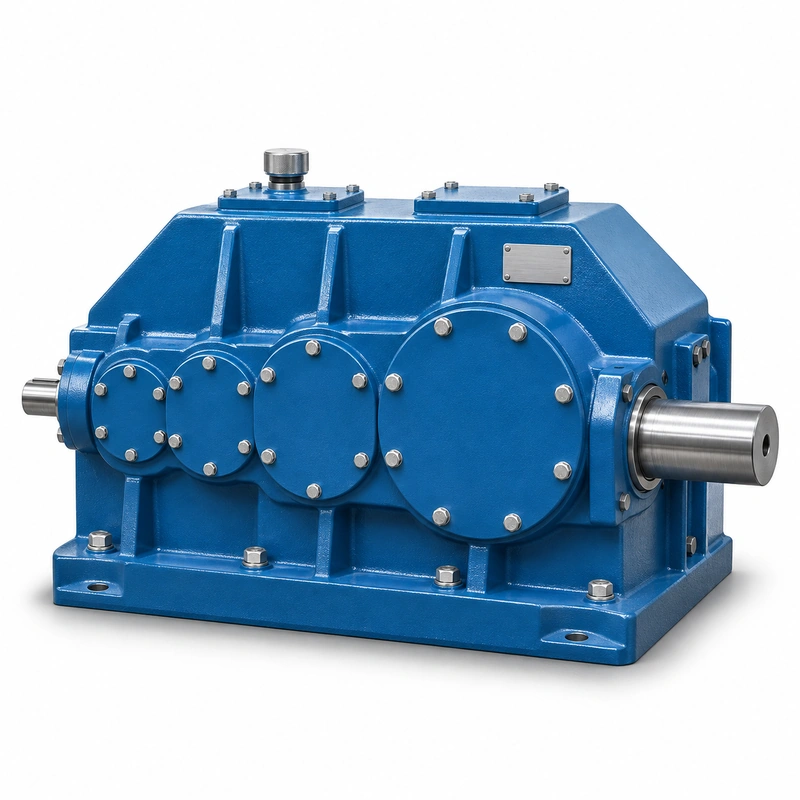
A three-stage QY3D ratio must be chosen with reference to the actual gearbox input speed and the output mechanism. If a drive is controlled by a variable-frequency motor, the usable operating window matters just as much as the nameplate reduction. Mechanical and thermal conditions under slow running may differ from a steady, nominal-speed calculation. Buyers replacing an older reducer should provide the real duty cycle instead of assuming the old motor rating remains appropriate.
Mounting and operating behavior of EP-QY3D
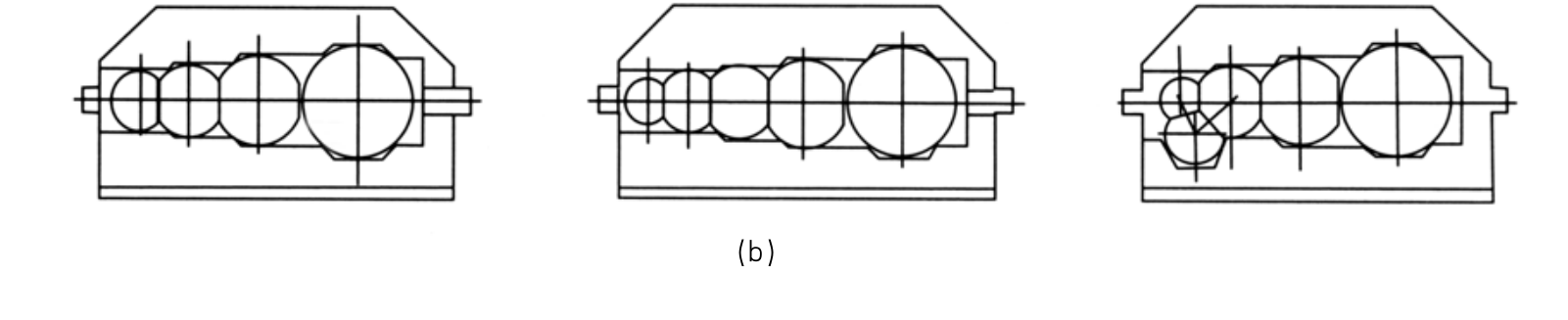
Shaft height and coupling
Measure the input and output shaft heights relative to the machined mounting surface. A gearbox that matches the desired ratio can still be unsuitable when the coupling cannot achieve acceptable angular and parallel alignment. Check whether the installed motor has enough adjustment travel and whether coupling guard clearance remains adequate after a replacement.
Foundation and fasteners
Compare base hole locations, fastener size, slot allowances and the load path from housing feet to the steel structure. Confirm whether horizontal shear is resisted by fitted bolts, stops or keys in the support system. The bolt circle alone does not indicate whether the reducer can be substituted without moving a motor or welding new support plates.
Drive train review
Send the motor power, base speed, control method, output shaft speed, coupling type and connected machine inertia. Where the transmission serves a drum, calculate the required mechanical torque using real load and drum radius. Determine gearbox rating using a duty assessment rather than dividing a single motor power figure by output speed.
QY3D specification and model identification
QY3D Crane Gearbox selection is defined by the combination of family construction, operating point and machine interfaces. The following data identifies the documented product family; a specific configuration must still be checked against its dimensional drawing and duty schedule.
| Parameter | Series-level reference |
|---|---|
| Mounting | Foot-mounted / base-supported QY3D configuration |
| Gear train | Three-stage QY family |
| Nominal ratio selection | 16–90 (configuration dependent) |
| Nominal centre distance | 160–800 mm family range |
| Drawing caution | The QY3D drawing is distinct from QY4D and QY34D |
The nominal centre-distance schedule below covers 15 named frame entries. It is a series index, not a statement that every combination of nominal ratio, shaft end and mounting exists at every size.
| Frame reference | Nominal centre distance | Ordering condition |
|---|---|---|
| Nominal centre a1 = 160 mm | 160 mm | Confirm ratio, interface and load rating for the requested version |
| Nominal centre a1 = 180 mm | 180 mm | Confirm ratio, interface and load rating for the requested version |
| Nominal centre a1 = 200 mm | 200 mm | Confirm ratio, interface and load rating for the requested version |
| Nominal centre a1 = 225 mm | 225 mm | Confirm ratio, interface and load rating for the requested version |
| Nominal centre a1 = 250 mm | 250 mm | Confirm ratio, interface and load rating for the requested version |
| Nominal centre a1 = 280 mm | 280 mm | Confirm ratio, interface and load rating for the requested version |
| Nominal centre a1 = 315 mm | 315 mm | Confirm ratio, interface and load rating for the requested version |
| Nominal centre a1 = 355 mm | 355 mm | Confirm ratio, interface and load rating for the requested version |
| Nominal centre a1 = 400 mm | 400 mm | Confirm ratio, interface and load rating for the requested version |
| Nominal centre a1 = 450 mm | 450 mm | Confirm ratio, interface and load rating for the requested version |
| Nominal centre a1 = 500 mm | 500 mm | Confirm ratio, interface and load rating for the requested version |
| Nominal centre a1 = 560 mm | 560 mm | Confirm ratio, interface and load rating for the requested version |
| Nominal centre a1 = 630 mm | 630 mm | Confirm ratio, interface and load rating for the requested version |
| Nominal centre a1 = 710 mm | 710 mm | Confirm ratio, interface and load rating for the requested version |
| Nominal centre a1 = 800 mm | 800 mm | Confirm ratio, interface and load rating for the requested version |
Hoisting versus travelling
For a hoisting transmission, explain starting torque, load holding and brake sequencing. For a travel mechanism, describe acceleration, wheel load, shock and repeated reversing. Those mechanisms impose different duty patterns and should not be treated as equivalent simply because the QY3D housing size and nominal ratio are similar.
Oil and service access
Check the oil-fill, drain and inspection locations with the gearbox installed. Some retrofit positions leave little access beside a motor base or guard. Plan the service side before foundation fabrication, and review whether the installed orientation requires a different fill quantity or breather location.
Incoming inspection
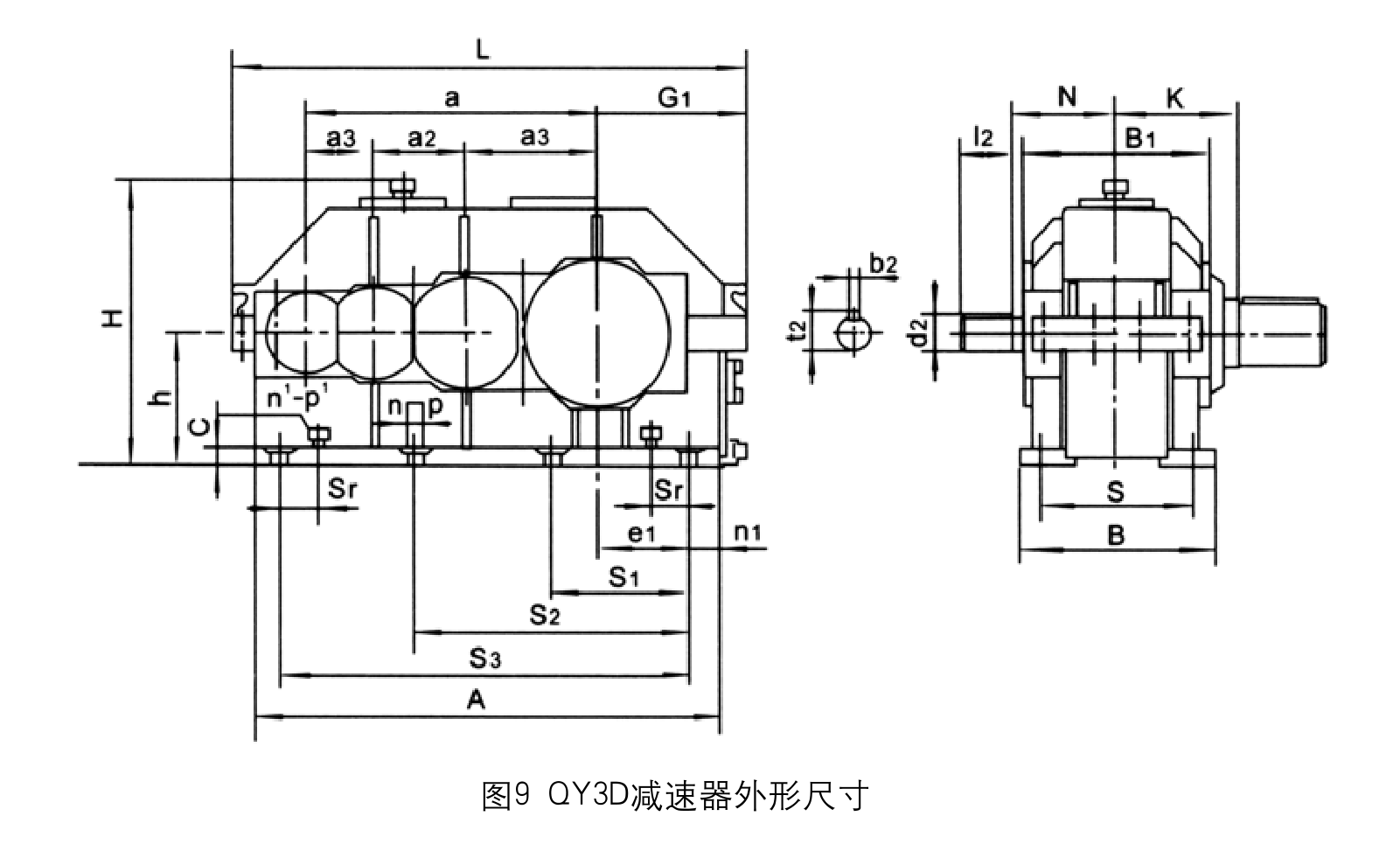
Verify principal dimensions against the approved drawing before fitting: foot-to-foot distance, centre heights, shaft diameters, flange location and keyway dimensions. Rotate the shafts by hand, protect seals during lifting, and confirm any specified accessories. A supplier quotation should explicitly say which mating parts are and are not included.
Shaft end and keyway
Distinguish journal diameter from keyway depth and usable engagement length. A hub can slide on a shaft and still be unsafe because the key is undersized or the hub overhang changes bearing reaction. Request the matching coupling half or a dimensioned hub sketch when quoting the shaft extension.
What the engineer must resolve before purchase
For an EP-QY3D installation, the main decision concerns foundation footprint, shimming and coupling centerline. A reused foundation may save fabrication time, but only after its condition and fastener capacity have been assessed. The best starting point is the actual machine arrangement, the operating load and the requested output speed.
Select
Confirm the true mechanical work point for QY3D Crane Gearbox: input speed, demanded output torque and the dynamic events that govern component loading.
Measure
Use the QY3D dimensional drawing to validate the installation envelope, shaft interfaces, mounting features and clearances on the actual machine.
Integrate
Match the selected drive with the connected motor, brake, coupling and supporting crane structure. Treat fit and control as one application.
Maintain
Plan access for lubrication, seals, inspection and removal. A compatible gearbox should also be practical to service after the crane is installed.
Swapping a reducer on a welded pedestal
Check the measured bolt coordinates and height of the old welded seat before confirming a foot-mounted housing. The motor may sit on the same bed and require adjustment. Consider lifting clearance and coupling disassembly space to keep the crane repair practicable.
Foot mounting applications and practical checks
- Bridge crane drum drive with floor-mounted transmission: describe the working load and mechanical interface before defining the reducer or gearmotor variant.
- Travel drives fitted to engineered machine pedestals: describe the working load and mechanical interface before defining the reducer or gearmotor variant.
- Maintenance replacements on existing bolted bases: describe the working load and mechanical interface before defining the reducer or gearmotor variant.
Drawing inputs for a foundation-mounted gearbox
- Base plate hole pitch and pattern: include the appropriate drawing, measured value, operating cycle or connection detail.
- Installed shaft centre heights: include the appropriate drawing, measured value, operating cycle or connection detail.
- Motor location and adjustment allowance: include the appropriate drawing, measured value, operating cycle or connection detail.
- Current coupling bore and keyway: include the appropriate drawing, measured value, operating cycle or connection detail.
- Output speed and duty torque: include the appropriate drawing, measured value, operating cycle or connection detail.
- Crane support drawing: include the appropriate drawing, measured value, operating cycle or connection detail.
- Available oil service access: include the appropriate drawing, measured value, operating cycle or connection detail.
- Required quantity and destination: include the appropriate drawing, measured value, operating cycle or connection detail.
Commercial enquiry for the QY3D series
Ever Power can discuss model identification, interface drawings and practical order quantities for the QY3D Crane Gearbox. Confirmed product configuration, lead time and delivery terms belong in the quotation. Trial and mixed-model requests can be assessed against the total order value.
To compare related drive families, explore the industrial drive product range. The company overview explains the supplier context for engineering and procurement enquiries.
Frequently asked questions about EP-QY3D
Is the QY3D footprint identical to QY4D or QY34D?
No such interchangeability should be assumed. The drawings are separate and the gear stage arrangement affects overall geometry. Supply the actual QY3D base and shaft measurements for the ordered size.
What should be checked before reusing the existing foundation?
Inspect the base for levelness, cracks and distortion; measure holes, shaft height and adjustment range. Check the reducer mass and torque-reaction support scheme rather than relying on the outside casing length.
Can the gearbox be selected from motor power alone?
Motor power is one input, but the driven torque, load spectrum, starts per hour, output speed and shaft loading also matter. The duty must be reviewed before treating a motor-to-gearbox match as suitable.
How does a trial order work for a customized gearbox for EP-QY3D?
For a suitable trial build, a new customer may request 1–5 samples. A 1–2-piece production order can sometimes be accommodated with a higher per-unit cost. Different gear-unit models may be combined in one commercial order if the overall minimum order value is around USD 1,500. Final MOQ depends on the configuration. For this product, quote preparation should also address foundation footprint, shimming and coupling centerline and the requested quantity.
What production schedule and Incoterms should be used for planning for EP-QY3D?
Indicative production windows are 10–25 working days for standard units, 20–45 for customized components and 45–120 for project equipment. Confirm the date in the accepted quotation. EXW, FOB, CIF and DAP are commonly discussed; FCA, CFR, CPT, CIP and DDP can be reviewed for the actual destination and contract. Schedule confirmation follows review of the QY3D interface and duty requirements.
Confirm a foot-mounted crane drive
Send your machine foundation layout, motor data and shaft interfaces. An EP-QY3D enquiry can be reviewed for the mounting arrangement, ratio and service duty so that the intended gearbox is defined before manufacture.