
Oil observed on a housing may have traveled from a vent, joint or shaft seal; finding the first wet point is essential. Replacing the nearest visible gasket can miss the actual defect. Refer to the gearbox seal leakage guidance. Record the earliest wetting location and any oil trail. Restore manufacturer-approved vent function.
Inspect pressure and vent paths
Investigate thermal stress
Monitor after normal load returns
Clean and trace the first leak point
Oil flows across the surface and can pool far from the failed seal; a wet base plate may originate at the upper breather rather than a lower housing gasket.
Replacing the nearest visible gasket can miss the actual defect; clean the stopped housing safely and inspect after a controlled run.
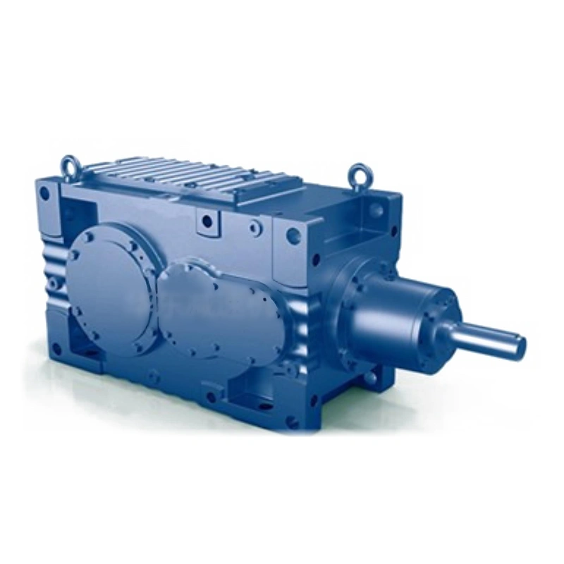
Record the earliest wetting location and any oil trail; identify the origin before selecting replacement parts; blind part replacement can increase maintenance cost without solving the leak.
Inspect pressure and vent paths
Internal pressure can rise as oil and gas warm in the gearbox; a blocked breather may force oil past otherwise serviceable seals.
Sealing a vent permanently may worsen leakage; check the correct breather fitting and position for the installed orientation.
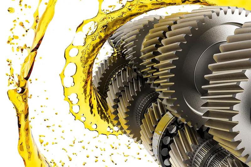
Observe whether oil mist or splash reaches the vent under load; restore manufacturer-approved vent function; a seal change cannot solve a persistent case-pressure cause.
Check shaft journal condition
A lip seal depends on a suitable clean running surface and shaft motion; a grooved or corroded shaft can damage a new seal immediately.
Installing a fresh lip on a worn track may produce only temporary improvement; inspect journal finish, wear track and shaft runout under isolation.
Compare measured surface condition with seal and shaft instructions; repair or sleeve the mating surface when qualified procedure requires; premature repeat leakage may reflect shaft condition rather than seal quality.
Confirm oil fill level
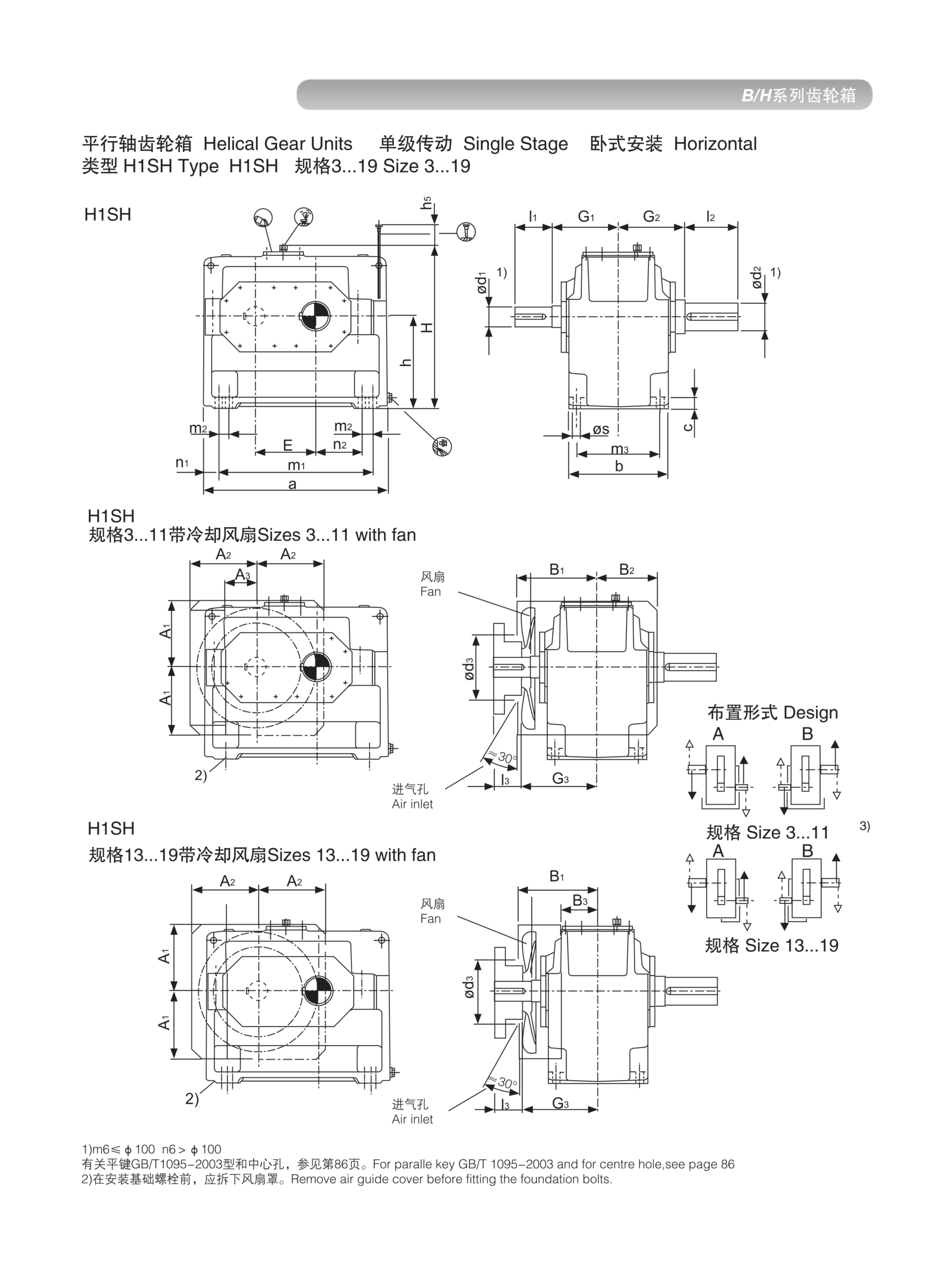
Overfilling increases churning and can increase leakage through breathers or seals; a housing rotated into a different mounting position may need a different level reference.
Using the wrong visible plug can cause chronic overfill; check documented mounting code and correct fill point.
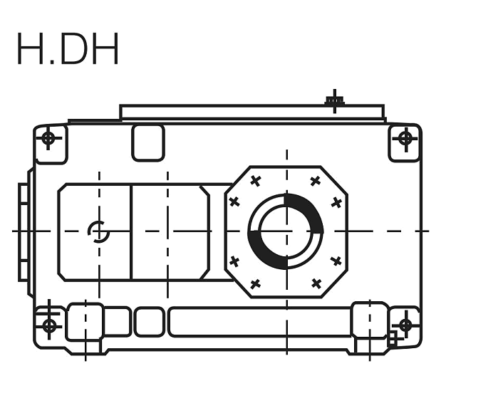
Measure level by the exact procedure for the installed unit; correct abnormal fill only using supplier instructions; adding more oil to a suspected leak may compound the problem.
Investigate thermal stress
Heat changes oil viscosity and can influence elastomer and shaft-seal performance; a newly overloaded drive may begin leaking after its housing temperature rises.
Changing seal material alone cannot correct an overloaded or overheated geartrain; record load and temperature before and after the leak began.
Inspect ventilation, oil condition and process changes; solve validated thermal causes with an approved remedy; a seal selected for the wrong operating temperature can fail repeatedly.
A newly overloaded drive may begin leaking after its housing temperature rises. Changing seal material alone cannot correct an overloaded or overheated geartrain. Examine the gearbox seal leakage layout example. Inspect ventilation, oil condition and process changes. Solve validated thermal causes with an approved remedy.
Reduce external abrasion
Dust, grit and pressure washdown can damage an otherwise suitable output seal; a shaft near a material transfer point may carry particles into the lip contact.
An open seal location may require machine-level shielding; review dust pathways, shaft guards and cleaning direction.
Specify actual exposure and cleaning agents for supplier review; use verified seal and guarding arrangements for the installation; a housing catalog protection label does not prove every external shaft location is sealed.
Install replacement parts correctly
Seals must seat without damaging their lip or distorting the housing; a misplaced spring or scratched shaft can cause immediate leakage after repair.
Improvised installation tools can create new damage; follow the exact seal installation and surface preparation instructions.
Check correct orientation and any required lubricant during assembly; verify post-repair leak tightness under the applicable duty; a clean appearance before startup is not evidence of a successful repair.
Monitor after normal load returns
A repaired unit should be inspected under temperature and shaft speed comparable to the original leak; a short no-load run may be dry even if hot production recreates the fault.
Closing the work order too early loses valuable fault evidence; inspect the repair region at controlled load and stable heat.
Record final oil level, external condition and any remaining seepage; accept only a repair meeting the defined cleanliness and leakage criteria; trend records distinguish genuine resolution from temporary masking.
Illustrative engineering scenario: A factory gearbox showing new lubricant traces around its output
A maintenance operator finds oil beneath a helical gearbox after a night shift. The first instinct is to replace the output shaft seal, because it is the nearest visible circular part. However, after safe isolation and cleaning, the technician finds that fresh lubricant appears higher up near the breather during a controlled restart. Oil has traveled down the side of the housing before reaching the floor. The team checks whether the breather is blocked or incorrectly placed for the actual mounting orientation and whether the unit has been overfilled. An oil-level mistake during recent service may explain the condition better than a failed output seal.
Suppose the leak does instead originate at the output journal. A replacement lip seal may not work if the shaft has an abrasive wear track, excessive runout or a damaged surface. The maintenance procedure includes inspecting the journal and reviewing the seal specification and installed environmental exposure. Fine material dust from the nearby conveyor may reach the lip; frequent washdown may expose the shaft to water. Those issues can call for an approved guard, material or sealing adjustment, but no improvement should be assumed without documentation for the actual machine. The crew avoids installing a higher-pressure or different elastomer seal without checking compatibility.
After repair, the correct fill level is confirmed for the unit orientation. The equipment runs first under a controlled safety procedure and then under representative loaded operation. The team observes the repaired region at normal working temperature, not merely while the housing is cold and stationary. A recorded dry result after a short free run is only preliminary; the oil leak that prompted investigation may require time to reappear. The maintenance record states the first wetting point, confirmed cause, replaced components and follow-up result. This turns a nuisance leak into a traceable engineering correction rather than an endless cycle of seal replacement.
Leaks that recur only after pressure washing deserve a different inspection pathway. Note water direction, the time since cleaning, and whether milky oil or a blocked vent is present. The plant should not presume that a generic protection marking applies to the assembled gearbox, motor and exposed output shaft in the same way. Check the actual seal arrangement and guarding against the cleaning method. A remedial measure should then be validated through the same washdown and production cycle that originally produced the symptom.
Five-stage review for a factory gearbox showing new lubricant traces around its output
- Clean and trace the first leak pointClean the stopped housing safely and inspect after a controlled run. Identify the origin before selecting replacement parts.
- Inspect pressure and vent pathsObserve whether oil mist or splash reaches the vent under load. A seal change cannot solve a persistent case-pressure cause.
- Confirm oil fill levelCheck documented mounting code and correct fill point. Correct abnormal fill only using supplier instructions.
- Reduce external abrasionSpecify actual exposure and cleaning agents for supplier review. A housing catalog protection label does not prove every external shaft location is sealed.
- Monitor after normal load returnsInspect the repair region at controlled load and stable heat. Accept only a repair meeting the defined cleanliness and leakage criteria.
Engineering comparison matrix: helical gearbox leaking oil shaft seal diagnosis
| Engineering question | Evidence to collect | Review decision |
|---|---|---|
| Clean and trace the first leak point | Record the earliest wetting location and any oil trail. | Identify the origin before selecting replacement parts. |
| Inspect pressure and vent paths | Observe whether oil mist or splash reaches the vent under load. | Restore manufacturer-approved vent function. |
| Check shaft journal condition | Compare measured surface condition with seal and shaft instructions. | Repair or sleeve the mating surface when qualified procedure requires. |
| Confirm oil fill level | Measure level by the exact procedure for the installed unit. | Correct abnormal fill only using supplier instructions. |
| Investigate thermal stress | Inspect ventilation, oil condition and process changes. | Solve validated thermal causes with an approved remedy. |
| Reduce external abrasion | Specify actual exposure and cleaning agents for supplier review. | Use verified seal and guarding arrangements for the installation. |
Frequently Asked Questions
Why does oil appear below a shaft seal even when the seal is intact?
Can overfilling a helical gearbox cause leaks?
Why does a new lip seal sometimes leak quickly?
How do you verify that a gearbox leak repair worked?
What makes a final review credible for a factory gearbox showing new lubricant traces around its output?
A misplaced spring or scratched shaft can cause immediate leakage after repair. When comparing actual mounting geometry, use the gearbox seal leakage configuration options. Check correct orientation and any required lubricant during assembly.
Inspect the repair region at controlled load and stable heat. For an engineering quotation that records the open conditions, contact the technical team about gearbox seal leakage. Accept only a repair meeting the defined cleanliness and leakage criteria.
Engineering sources for Helical Gearbox Oil Leak Diagnosis and Seal Protection
For the helical gearbox oil leak diagnosis and seal protection workflow, consult these reference documents alongside the actual model installation manual:
- Helical Gearbox Oil Leak Diagnosis and Seal Protection: SEW-EURODRIVE, Lubricant tables (analysis).
- Helical Gearbox Oil Leak Diagnosis and Seal Protection: SEW-EURODRIVE, Dimension sheet information (interface review).
- Helical Gearbox Oil Leak Diagnosis and Seal Protection: SEW-EURODRIVE, Change of mounting position (acceptance checks).