
Solid and hollow output connections trade coupling flexibility against integration depth and reaction support. A matching nominal diameter cannot alone establish fit. Refer to the solid and hollow shaft interfaces guidance. Record tolerances, usable engagement and shaft shoulder positions. Approve torque transfer on documented dimensions and materials.
Clarify the torque transfer interface
Design torque reaction for the body
Order exact variant and accessories
Clarify the torque transfer interface
A solid output couples to the driven machine while a hollow bore encloses part of its shaft; the choice changes where contact pressure and axial retention occur.
A matching nominal diameter cannot alone establish fit; show full section views of both proposed shaft connections.
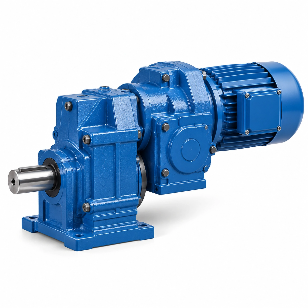
Record tolerances, usable engagement and shaft shoulder positions; accept only an approved connection with defined torque path; confusing shaft style can turn a compact assembly into a difficult retrofit.
Analyze keyed engagement
A keyed bore depends on key profile, keyseat and meaningful engagement length; short engagement may concentrate pressure and promote fretting.
A key that slides into place does not prove rated torque capacity; compare key height, width and fit with the actual mating shaft.
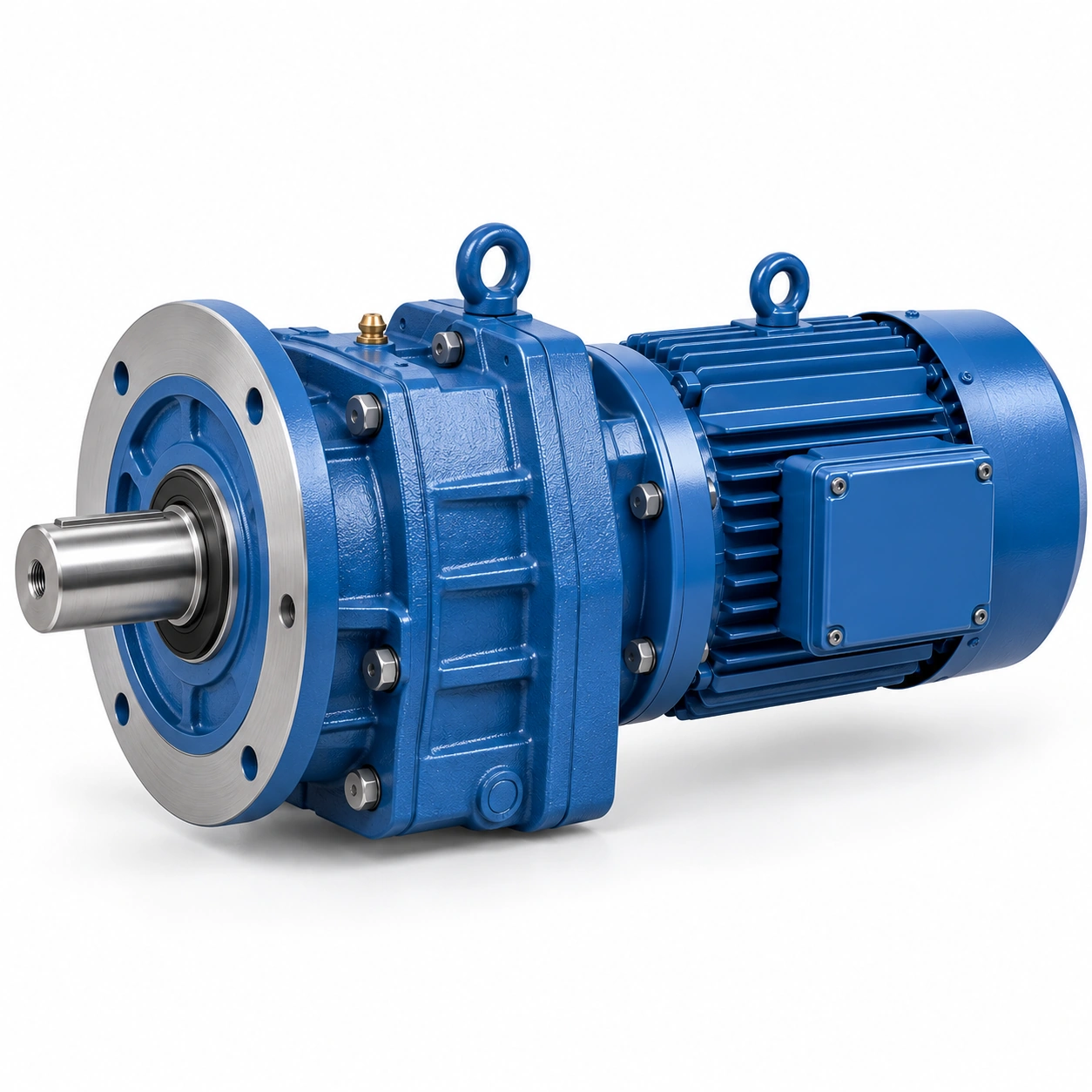
Record permitted contact pressure and any required end retention; approve torque transfer on documented dimensions and materials; an oversized key or loose fit can damage both shaft and hub.
Evaluate shrink-disc alternatives
Keyless locking transmits torque through controlled friction under clamping force; surface condition, fit and tightening order determine the result.
Unapproved lubricants or bolt torques may reduce the connection reliability; obtain the exact locking-device assembly procedure.
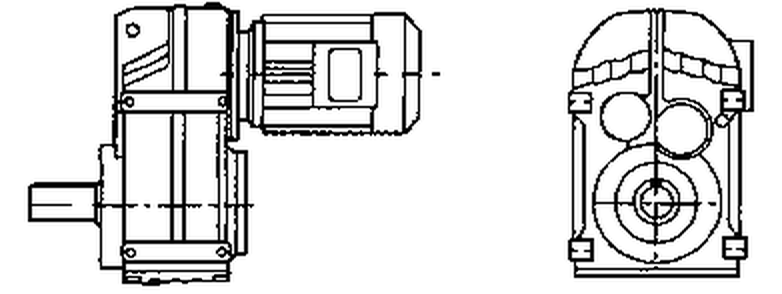
Record shaft finish, cleanliness and fastener tightening sequence; use a validated connection from the authorized supplier; a generic bolt torque chart cannot replace a keyed or keyless joint design.
Keep the machine shaft supported
A hollow gearbox may be shaft-mounted but its bearings are not unlimited external supports; the driven machine can transmit bending through the bore if bearing positions are poorly chosen.
Eliminating a coupling without load analysis may increase bearing stress; draw all fixed and floating supports and output load positions.
Request combined Fr and Fa capability for the intended load path; approve external support where necessary; a compact housing is not evidence of a permissible unsupported machine shaft.
Design torque reaction for the body
A hollow shaft drive still exerts housing reaction torque in the opposite direction; a torque arm can restrain rotation while allowing controlled alignment movement.
Fastening the housing rigidly at several unintended points may overconstrain the assembly; calculate reaction torque and locate the allowed restraint direction.
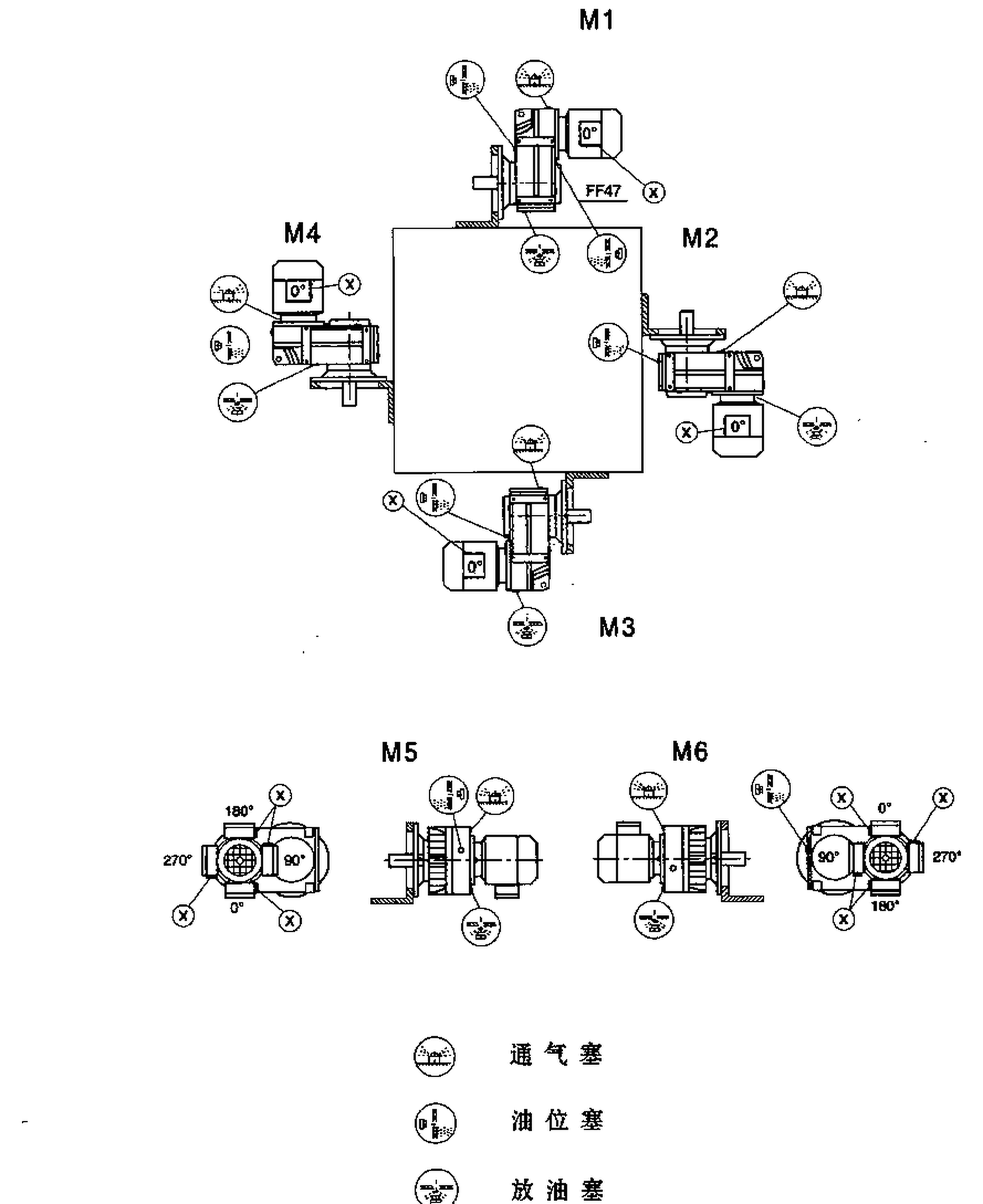
Show arm length and joint freedom on the layout; use the manufacturer-defined reaction arrangement; a misplaced arm can introduce housing forces unrelated to useful output torque.
A torque arm can restrain rotation while allowing controlled alignment movement. Fastening the housing rigidly at several unintended points may overconstrain the assembly. Examine the solid and hollow shaft interfaces layout example. Show arm length and joint freedom on the layout. Use the manufacturer-defined reaction arrangement.
Plan shaft withdrawal after service
A hollow bore may become difficult to remove after long exposure to moisture; corrosion and fretting complicate servicing a unit fitted directly on the machine shaft.
A layout with no puller space can cause excessive teardown time; reserve axial extraction room and safe lifting or jacking points.
Specify removal threads, sleeves and tool access where supplied; demonstrate an acceptable maintenance method at design review; installation convenience should not create an impossible removal procedure.
Compare coupling behavior
Solid-shaft units may use a separate flexible coupling that permits defined misalignment; coupling stiffness and installation alignment affect bearing reactions.
Removing a coupling does not automatically eliminate alignment risk; measure nominal shaft centerlines and thermal growth allowance.
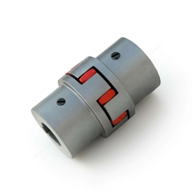
Check coupling alignment tolerance or direct shaft fit as applicable; select a load path with the needed degrees of freedom; a shaft style may require structural redesign even if the gear ratio is unchanged.
Order exact variant and accessories
Housing series often includes multiple flange, bore, shaft and motor arrangements; procurement may omit shrink discs, torque arms or extraction hardware unless listed.
Two similarly titled units can have different installed interfaces; include full gearbox code, interface drawing and mounting accessories in RFQ.
Verify actual output construction and retaining elements in the supplier offer; check the delivered unit against the approved interface schedule; a generic description of a parallel shaft gearbox is not an order specification.
Illustrative engineering scenario: A new oem drive interface between reducer and driven machinery
A machine builder compares two configurations for an industrial roller drive. Option one uses a solid reducer output coupled to an independently supported roller shaft. Option two places an F-series hollow-output gearbox directly on the roller shaft. The second configuration may reduce overall length and eliminate a coupling, but it also transfers the output interface into a close-fitting bore and changes the housing torque reaction. Engineering prepares cross-sections of both options, including the key or locking connection, shaft shoulder, axial retention and any separate fixed or floating bearings. A single matching bore diameter is not sufficient evidence of an appropriate fit.
Suppose the direct-mounted option uses a keyed connection. The torque path goes through the key and engaged bore length; contact conditions matter, especially if the machine reverses frequently. If a shrink-type locking device is selected instead, surface cleanliness, assembly sequence and clamping bolt instructions become part of the accepted design. In either case, the design must provide a proper reaction restraint for the gearbox housing. A torque arm can carry a moment without necessarily becoming a rigid extra bearing, but only if its geometry follows the approved installation method. It also needs access for inspection after service.
Now imagine the roller shaft corrodes slightly during years of washdown. A hollow-output gearbox that went on easily may need controlled extraction with jacking tools or a puller. The CAD review therefore reserves withdrawal space and lifting access. A conventional solid-shaft option may be easier to remove but could require more coupling and alignment work. The correct decision compares duty, shaft load, fit, structural reaction, maintenance and usable machine space together. Buying from a photo or broad catalogue description risks selecting an interface that works only on the day of installation.
A practical purchasing comparison also lists what arrives in each quotation. A direct-mounted hollow-shaft gearmotor may require a specific torque arm, retaining plate or locking assembly that a bare reducer price does not include. The solid-shaft solution may require a coupling guard or a separate bearing support. Unless these accessories are normalized, price comparisons are not technical comparisons. The machine drawing and offer should refer to the same retention and reaction components before approval.
For equipment with frequent reversals, the shaft joint should also be assessed for the direction and timing of torque changes. A fit that works on a steady conveyor may behave differently in a reversing indexer. The engineering team records those cycling conditions for the chosen retention method and confirms whether the assembly procedure places special restrictions on repeated torque reversal. A direct-mounted arrangement should be selected for the real duty, not merely for its neat appearance.
Five-stage review for a new OEM drive interface between reducer and driven machinery
- Clarify the torque transfer interfaceShow full section views of both proposed shaft connections. Accept only an approved connection with defined torque path.
- Analyze keyed engagementRecord permitted contact pressure and any required end retention. An oversized key or loose fit can damage both shaft and hub.
- Keep the machine shaft supportedDraw all fixed and floating supports and output load positions. Approve external support where necessary.
- Plan shaft withdrawal after serviceSpecify removal threads, sleeves and tool access where supplied. Installation convenience should not create an impossible removal procedure.
- Order exact variant and accessoriesInclude full gearbox code, interface drawing and mounting accessories in RFQ. Check the delivered unit against the approved interface schedule.
Engineering comparison matrix: solid shaft vs hollow shaft helical gearbox
| Engineering question | Evidence to collect | Review decision |
|---|---|---|
| Clarify the torque transfer interface | Record tolerances, usable engagement and shaft shoulder positions. | Accept only an approved connection with defined torque path. |
| Analyze keyed engagement | Record permitted contact pressure and any required end retention. | Approve torque transfer on documented dimensions and materials. |
| Evaluate shrink-disc alternatives | Record shaft finish, cleanliness and fastener tightening sequence. | Use a validated connection from the authorized supplier. |
| Keep the machine shaft supported | Request combined Fr and Fa capability for the intended load path. | Approve external support where necessary. |
| Design torque reaction for the body | Show arm length and joint freedom on the layout. | Use the manufacturer-defined reaction arrangement. |
| Plan shaft withdrawal after service | Specify removal threads, sleeves and tool access where supplied. | Demonstrate an acceptable maintenance method at design review. |
Frequently Asked Questions
Is a hollow-shaft gearbox always more compact?
Does matching nominal shaft diameter prove a hollow bore fit?
What must be considered when using a shrink-disc connection?
What is the maintenance disadvantage of some hollow-shaft installations?
What makes a final review credible for a new OEM drive interface between reducer and driven machinery?
Coupling stiffness and installation alignment affect bearing reactions. When comparing actual mounting geometry, use the solid and hollow shaft interfaces configuration options. Check coupling alignment tolerance or direct shaft fit as applicable.
Include full gearbox code, interface drawing and mounting accessories in RFQ. For an engineering quotation that records the open conditions, contact the technical team about solid and hollow shaft interfaces. Check the delivered unit against the approved interface schedule.
Engineering sources for Solid Shaft vs Hollow Shaft Helical Gearboxes for OEM Design
For the solid shaft vs hollow shaft helical gearboxes for oem design workflow, consult these reference documents alongside the actual model installation manual:
- Solid Shaft vs Hollow Shaft Helical Gearboxes for OEM Design: SEW-EURODRIVE, Dimension sheet information (analysis).
- Solid Shaft vs Hollow Shaft Helical Gearboxes for OEM Design: SKF, Bearing App documentation (interface review).
- Solid Shaft vs Hollow Shaft Helical Gearboxes for OEM Design: SEW-EURODRIVE, Change of mounting position (acceptance checks).