
A vibration trend is most informative when sensor location, speed and process load are consistent. Moving the sensor between different structures invalidates simple trend comparisons. Refer to the gearbox vibration monitoring guidance. Record axes, mounting method and sensor specifications. Use those reference conditions when evaluating deterioration.
Choose rigid measuring points
Account for variable process load
Investigate mounting and alignment
Choose rigid measuring points
The housing near a bearing provides more useful repeatability than a thin outer guard; a flexible fan shroud can vibrate strongly without representing the bearing condition.
Moving the sensor between different structures invalidates simple trend comparisons; select marked bearing-housing points for repeatable measurement.
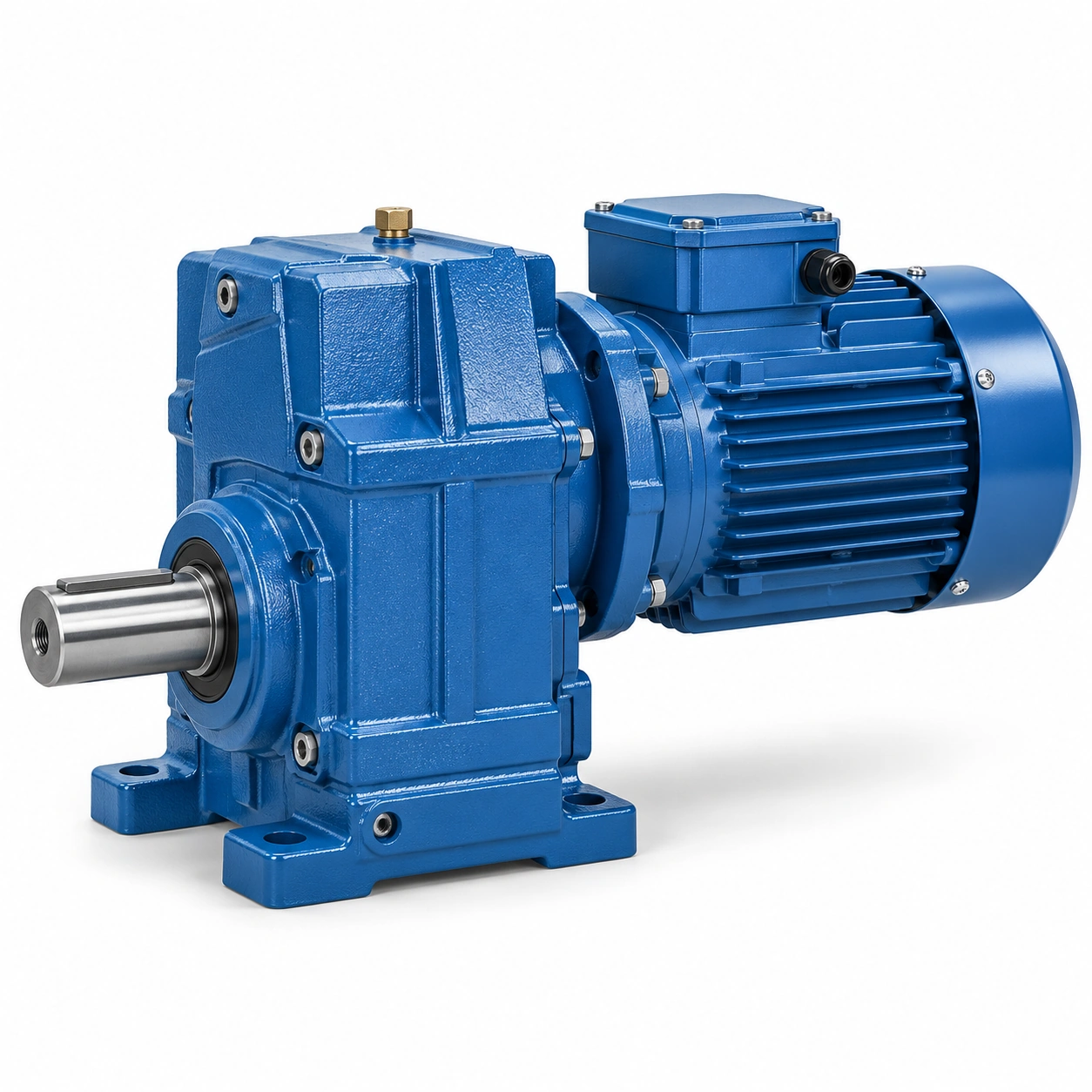
Record axes, mounting method and sensor specifications; compare readings only where installation and processing are equivalent; a high value at a loose panel can distract from an otherwise stable reducer.
Collect healthy operating baselines
A new unit should be observed under the duty that it will normally experience; vibration during a warm loaded shift may differ from vibration during cold no-load acceptance.
A baseline without speed and load makes later changes difficult to interpret; take commissioning readings at representative torque and temperature.
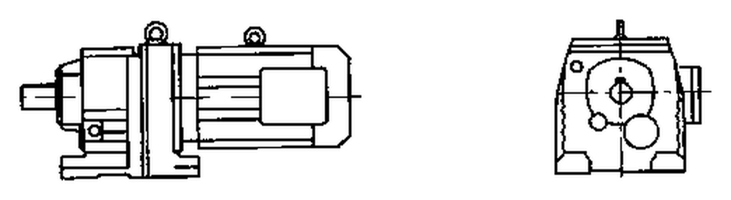
Store motor frequency, output rpm and material throughput alongside waveforms; use those reference conditions when evaluating deterioration; an absolute amplitude from an unknown condition is weak failure evidence.
Distinguish shaft and mesh orders
Rotational faults may track shaft frequency while mesh-related components occur at higher multiples; several shaft and gear-stage frequencies can overlap with resonances.
One prominent spectrum peak does not uniquely identify a damaged component; obtain the machine shaft speeds and available gearing details.
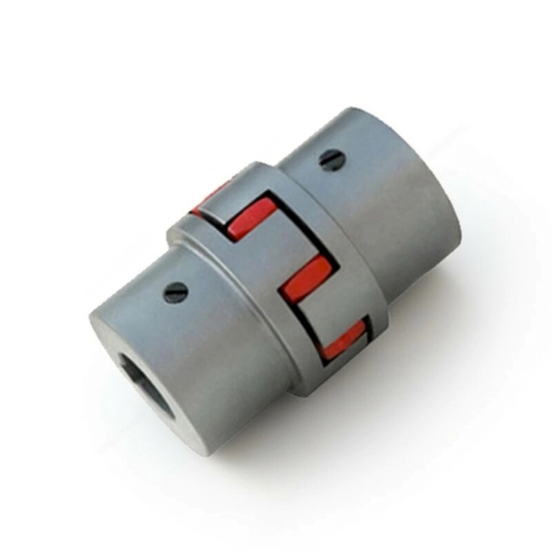
Use tachometer or validated speed input to interpret frequencies; make hypotheses that account for the full drivetrain before parts replacement; misidentified orders can send maintenance toward the wrong bearing or mesh.
Account for variable process load
Machinery throughput and motor control cause genuine vibration changes unrelated to wear; a conveyor filled with material often has different excitation from an empty one.
Comparing unlike recipes can create false-positive alarms; label every record with process state and current trend.

Compare samples under similar torque, temperature and rpm conditions; treat consistent deterioration across comparable runs as stronger evidence; a larger vibration number need not mean a new component fault.
Combine independent indicators
Oil analysis, temperature, noise and current draw add context to vibration; a rising bearing vibration accompanied by leakage and heat deserves different priority from an isolated change.
Relying on only one sensor may overlook external mounting or control causes; trend multiple parameters at the same operating period.
Check recent service, alignment and lubricant changes when new vibration appears; escalate when independent indicators support the same developing fault; condition monitoring is diagnostic support, not a substitute for site safety judgment.
A rising bearing vibration accompanied by leakage and heat deserves different priority from an isolated change. Relying on only one sensor may overlook external mounting or control causes. Examine the gearbox vibration monitoring layout example. Check recent service, alignment and lubricant changes when new vibration appears. Escalate when independent indicators support the same developing fault.
Define action bands with the OEM
Alert and shutdown thresholds depend on the machine and local risk acceptance; a drive on a critical process line may use conservative escalation compared with a noncritical auxiliary.
Invented universal limits can either trip healthy machines or miss deterioration; agree on baseline-relative thresholds and response responsibilities.
Record monitoring method, review cadence and stop criteria; validate alarm logic against equipment-specific accepted standards and risk; a threshold without a response plan provides little practical protection.
Investigate mounting and alignment
Misalignment, soft foot and loose fasteners generate vibration outside the gearing itself; a coupling rebuilt after maintenance can change vibration at motor and gearbox bearings.
An internal gearbox diagnosis is premature without checking the structure; inspect mounting condition and alignment under safe isolation.
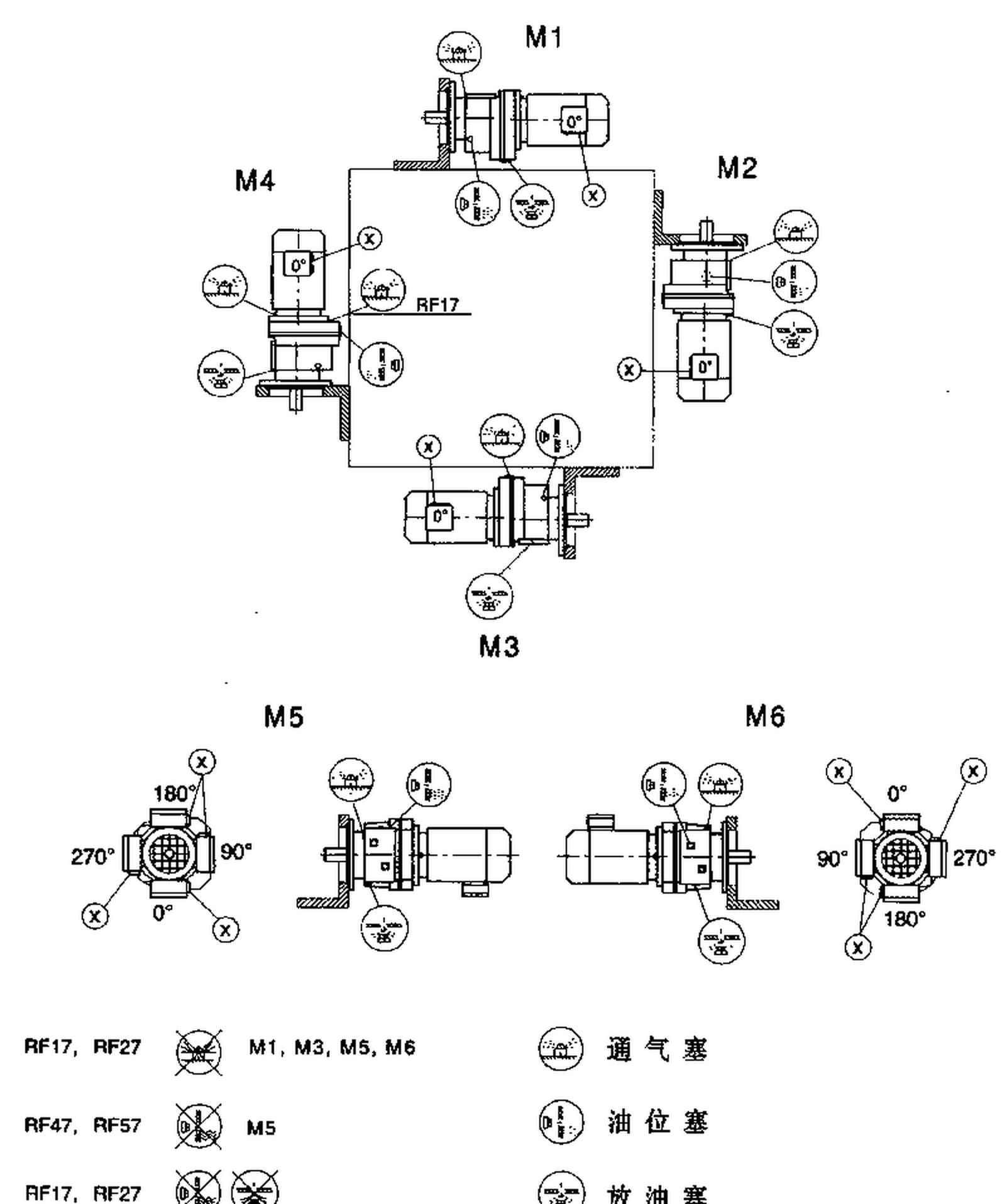
Compare motor, gearbox and driven-machine points for correlated behavior; repair confirmed external causes before stripping the gear train; unnecessary disassembly can introduce additional alignment errors.
Rebaseline after a repair
Changes to sensors, bearing parts or couplings may shift the normal vibration signature; a new reference should not erase evidence of the problem that motivated repair.
Without documented before-and-after data the success of a repair stays uncertain; repeat matched operating measurements following corrective work.
Preserve old and new baselines with configuration revisions; close the work order only when agreed trend and operating checks pass; unrecorded rebaselining can conceal repeated faults across maintenance cycles.
Illustrative engineering scenario: An industrial drive monitored for condition-based maintenance
A maintenance organization installs portable vibration sensors on several similar gear reducers. The first month of data appears inconsistent: one gearbox has a higher amplitude than another, yet both operate normally. Review shows that a technician placed the first sensor on the main bearing housing and the second on an adjacent thin guard. The two measurements are not mechanically equivalent. A repeatable program begins by marking rigid sensor positions, recording the measurement axis and fixing the acquisition method. Each recording also identifies speed and process load because a material-handling machine cannot be meaningfully compared across different production recipes without that context.
The gearbox nearest the loading chute later develops a slowly increasing vibration component at one running condition. The reliability engineer checks whether the same change appears in motor current, temperature or oil analysis. A new sound after a coupling replacement may indicate an external alignment problem rather than internal gear tooth damage. The team uses shaft-speed information to distinguish rotating orders from structural resonances, but avoids naming a damaged bearing solely from a single spectrum peak. Where gear-tooth or bearing condition is uncertain, a specialist may review the waveform, load trend and recent service history together.
The organization sets a staged response rather than one unsupported numerical threshold. A review alert prompts repeat measurement and physical inspection; a more severe, corroborated condition triggers the machine risk procedure. After an alignment repair, the crew repeats the test at the same load and rpm, retaining both the old and new reference data. That matters because deleting the old baseline would remove the proof of whether the intervention actually improved the observed condition. Condition monitoring succeeds when data is comparable and decisions are documented, not merely because the software produces colored graphs.
The data owner also reviews whether a sensor replacement, mounting method or firmware update has altered the measurement chain. When acquisition settings change, absolute readings may shift without any physical gearbox deterioration. That possibility belongs in the monitoring log, alongside shaft speed and production load. If a vibration alert cannot be reproduced under matched conditions, the result is an investigation item rather than a proven failure diagnosis; uncertain data should prompt repeat measurement before costly intervention.
An analyst should not confuse a spectrum label with a confirmed damaged part. The rotating machine may have several transmission elements that share harmonics or excite the same frame frequency. Recording tachometer speed and comparing multiple bearing positions can strengthen the hypothesis. Where an intervention is proposed, its expected effect should be stated in advance and then checked after the work. This prevents a monitoring program from becoming a sequence of unmeasured part changes.
Five-stage review for an industrial drive monitored for condition-based maintenance
- Choose rigid measuring pointsSelect marked bearing-housing points for repeatable measurement. Compare readings only where installation and processing are equivalent.
- Collect healthy operating baselinesStore motor frequency, output rpm and material throughput alongside waveforms. An absolute amplitude from an unknown condition is weak failure evidence.
- Account for variable process loadLabel every record with process state and current trend. Treat consistent deterioration across comparable runs as stronger evidence.
- Define action bands with the OEMRecord monitoring method, review cadence and stop criteria. A threshold without a response plan provides little practical protection.
- Rebaseline after a repairRepeat matched operating measurements following corrective work. Close the work order only when agreed trend and operating checks pass.
Engineering comparison matrix: helical gearbox vibration monitoring guide
| Engineering question | Evidence to collect | Review decision |
|---|---|---|
| Choose rigid measuring points | Record axes, mounting method and sensor specifications. | Compare readings only where installation and processing are equivalent. |
| Collect healthy operating baselines | Store motor frequency, output rpm and material throughput alongside waveforms. | Use those reference conditions when evaluating deterioration. |
| Distinguish shaft and mesh orders | Use tachometer or validated speed input to interpret frequencies. | Make hypotheses that account for the full drivetrain before parts replacement. |
| Account for variable process load | Compare samples under similar torque, temperature and rpm conditions. | Treat consistent deterioration across comparable runs as stronger evidence. |
| Combine independent indicators | Check recent service, alignment and lubricant changes when new vibration appears. | Escalate when independent indicators support the same developing fault. |
| Define action bands with the OEM | Record monitoring method, review cadence and stop criteria. | Validate alarm logic against equipment-specific accepted standards and risk. |
Frequently Asked Questions
Where should a gearbox vibration sensor be mounted?
What context should be stored with each vibration sample?
Can a frequency peak uniquely diagnose a damaged gear tooth?
How should monitoring thresholds be selected?
What makes a final review credible for an industrial drive monitored for condition-based maintenance?
A coupling rebuilt after maintenance can change vibration at motor and gearbox bearings. When comparing actual mounting geometry, use the gearbox vibration monitoring configuration options. Compare motor, gearbox and driven-machine points for correlated behavior.
Repeat matched operating measurements following corrective work. For an engineering quotation that records the open conditions, contact the technical team about gearbox vibration monitoring. Close the work order only when agreed trend and operating checks pass.
Engineering sources for Helical Gearbox Vibration Monitoring for Early Fault Detection
For the helical gearbox vibration monitoring for early fault detection workflow, consult these reference documents alongside the actual model installation manual:
- Helical Gearbox Vibration Monitoring for Early Fault Detection: SKF Evolution, Parallel condition monitoring (analysis).
- Helical Gearbox Vibration Monitoring for Early Fault Detection: SKF, Bearing App documentation (interface review).
- Helical Gearbox Vibration Monitoring for Early Fault Detection: SEW-EURODRIVE, Basic calculation process (acceptance checks).