
Lubrication planning must start from the reducer manual and actual mounting position, rather than a generic oil chart. Matching only viscosity on a storage drum may overlook seal and material compatibility. Refer to the gearbox oil selection guidance. Record oil grade, approval reference, temperature range and any special service classification. Choose a product satisfying all manufacturer conditions, not a single numeral.
Select by approved specification
Control moisture and particle entry
Connect lubrication to temperatures
Select by approved specification
Gear tooth contacts and rolling bearings depend on a lubricant with suitable film and additive behavior; a gearbox may require a different additive package from a nearby hydraulic unit.
Matching only viscosity on a storage drum may overlook seal and material compatibility; find the manufacturer lubrication section for the exact reducer type.
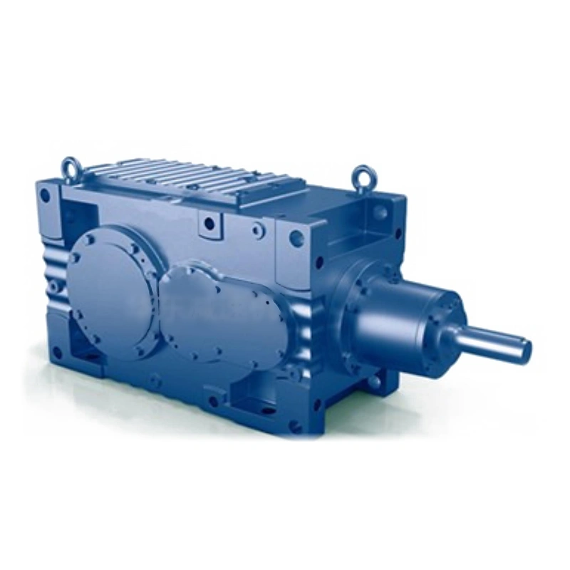
Record oil grade, approval reference, temperature range and any special service classification; use only the stated or separately authorized lubricant formulation; a convenient bulk lubricant can become a costly contamination event.
Understand viscosity notation
ISO viscosity classifications identify viscosity at a reference temperature, not a complete lubricant suitability; oil with the same ISO VG may differ in base stock, additives and low-temperature response.
Interpreting the number as an all-purpose specification is unreliable; check the full product name and approved viscosity grade.
Confirm startup temperature, steady temperature and the required lubricant approval; choose a product satisfying all manufacturer conditions, not a single numeral; the correct printed viscosity does not guarantee approved additives.
Use orientation-specific fill levels
Oil quantity changes when housing attitude changes relative to its fill and drain points; a machine assembled vertically may place an upper bearing above the splash region.
Filling until oil appears at an arbitrary hole can overfill or underfill the drive; verify the actual mounting position and designated level port.
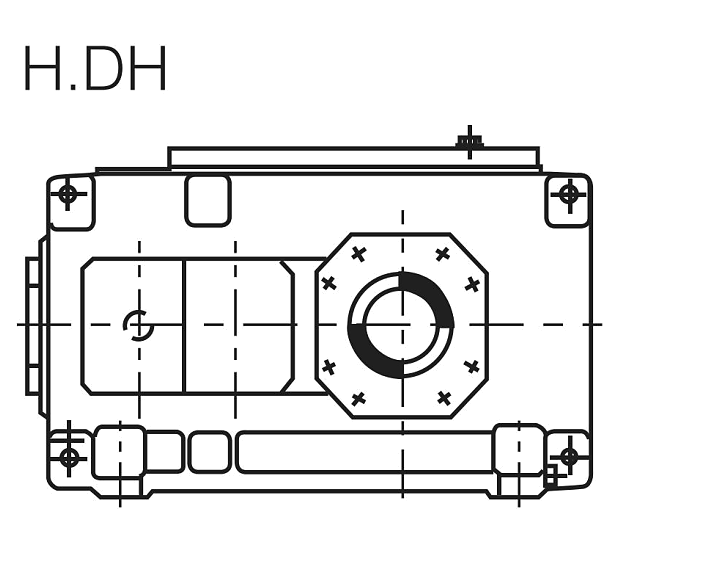
Record initial fill volume, sight-glass marks and correct vent location; confirm fill level with exact instructions for that installation orientation; excess oil can increase churning just as insufficient oil jeopardizes lubrication.
Control moisture and particle entry
Breathers, shaft seals and service tools provide possible paths for contamination; water from washdown may emulsify oil while abrasive dust damages bearing contacts.
A new oil drum does not guarantee that the transfer process remains clean; inspect vent position, seal integrity and clean transfer equipment.
Record visible water, particle trends and storage conditions; apply corrective exclusion measures alongside any oil replacement; repeated oil changes without sealing correction leave the cause untreated.
Use oil analysis intelligently
Particle count, water content and wear trends can reveal deterioration not obvious by eye; darkened oil alone does not diagnose tooth damage or determine the next service interval.
One isolated result is weaker than a comparable sampling history; establish a repeatable sampling point and clean sample bottle method.
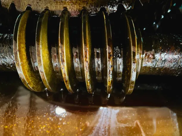
Track temperature, run hours, abnormal events and analytical results together; use changes from baseline to trigger targeted inspection and supplier review; an arbitrary color criterion can cause unnecessary oil changes or missed faults.
Darkened oil alone does not diagnose tooth damage or determine the next service interval. One isolated result is weaker than a comparable sampling history. Examine the gearbox oil selection layout example. Track temperature, run hours, abnormal events and analytical results together. Use changes from baseline to trigger targeted inspection and supplier review.
Prepare a safe drain and refill
A hot drive contains energy and possibly pressurized or contaminated lubricant; drain work may require guarding removal, isolation and spill containment.
Opening plugs on a running or inadequately isolated machine is unsafe; follow the machine lockout and cool-down procedure before handling oil.
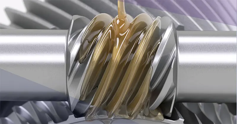
Confirm plug type, new seals, fill volume and environmental disposal plan; verify final oil level and vent condition before returning to duty; a rushed refill may leave dirt, leakage or an incorrect plug installed.
Connect lubrication to temperatures
Oil condition and operating heat interact with mechanical load and enclosure ventilation; repeated high temperature can accelerate oxidation and seal deterioration.
Simply switching to a thinner fluid may weaken the film on loaded contacts; check temperature trends under comparable load and ambient conditions.
Record measured oil temperature and the permitted range for the chosen lubricant; investigate load and cooling factors before changing approved oil; a surface temperature spot reading is not the same as oil bulk temperature.
Keep the service record useful
The record should help identify what changed before a leak or vibration complaint; a log with only the date but no oil identity cannot reconstruct a failure.
Missing run hours or abnormal events weakens reliability analysis; record date, run hours, lubricant, fill quantity and technician observation.
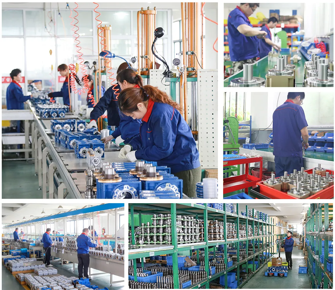
Store oil analysis references and any seal or breather repair alongside the job; use consistent records to adjust an evidence-backed maintenance plan; good traceability helps distinguish a product defect from an altered duty or service condition.
Illustrative engineering scenario: A scheduled lubrication program for industrial gear reducers
A maintenance team inherits several helical reducers installed in different orientations. The service schedule has a single line that says ‘fill with gear oil' and changes all units at the same calendar interval. This is not enough information for safe service. The planner starts by matching each asset number to a complete gearbox designation, approved mounting code and lubricant instruction. Where the manual lists alternative lubricant grades, the record should retain the conditions that govern the choice. The stockroom must also be able to distinguish two products of similar viscosity but different approval or additive characteristics.
One gearbox sits in a wet processing bay. Before its next change, the team finds evidence of moisture around the breather and persistent dust in the service area. Replacing the oil may remove contamination, but it will not close the entry path. The technician inspects seals, vent location and transfer equipment, then collects a consistent oil sample for analysis if the maintenance program supports it. The sampling point, run hours, oil identity and measured temperature are logged. This allows a later sample to be compared with a real baseline rather than the subjective statement that the oil looked dark.
For an actual service, the drive is isolated under the plant procedure and allowed to reach a safe handling condition. The approved fill and drain points are used for that mounting position. After refilling, the technician confirms level, breather arrangement and absence of new leakage under a controlled return to operation. The maintenance manager records any departures from the manual and sends unanswered compatibility questions to the supplier. The result is a lubricant plan that can survive staff changes and future fault investigations. It also avoids pretending that one viscosity number or oil-change interval is valid for every reducer in the plant.
Five-stage review for a scheduled lubrication program for industrial gear reducers
- Select by approved specificationFind the manufacturer lubrication section for the exact reducer type. Use only the stated or separately authorized lubricant formulation.
- Understand viscosity notationConfirm startup temperature, steady temperature and the required lubricant approval. The correct printed viscosity does not guarantee approved additives.
- Control moisture and particle entryInspect vent position, seal integrity and clean transfer equipment. Apply corrective exclusion measures alongside any oil replacement.
- Prepare a safe drain and refillConfirm plug type, new seals, fill volume and environmental disposal plan. A rushed refill may leave dirt, leakage or an incorrect plug installed.
- Keep the service record usefulRecord date, run hours, lubricant, fill quantity and technician observation. Use consistent records to adjust an evidence-backed maintenance plan.
Engineering comparison matrix: helical gearbox lubrication maintenance oil
| Engineering question | Evidence to collect | Review decision |
|---|---|---|
| Select by approved specification | Record oil grade, approval reference, temperature range and any special service classification. | Use only the stated or separately authorized lubricant formulation. |
| Understand viscosity notation | Confirm startup temperature, steady temperature and the required lubricant approval. | Choose a product satisfying all manufacturer conditions, not a single numeral. |
| Use orientation-specific fill levels | Record initial fill volume, sight-glass marks and correct vent location. | Confirm fill level with exact instructions for that installation orientation. |
| Control moisture and particle entry | Record visible water, particle trends and storage conditions. | Apply corrective exclusion measures alongside any oil replacement. |
| Use oil analysis intelligently | Track temperature, run hours, abnormal events and analytical results together. | Use changes from baseline to trigger targeted inspection and supplier review. |
| Prepare a safe drain and refill | Confirm plug type, new seals, fill volume and environmental disposal plan. | Verify final oil level and vent condition before returning to duty. |
Frequently Asked Questions
Can ISO VG grade alone specify gearbox oil?
Is the oil quantity identical for every mounting position?
Should oil be changed just because it looks dark?
What must be recorded after a gearbox oil change?
What makes a final review credible for a scheduled lubrication program for industrial gear reducers?
Repeated high temperature can accelerate oxidation and seal deterioration. When comparing actual mounting geometry, use the gearbox oil selection configuration options. Record measured oil temperature and the permitted range for the chosen lubricant.
Record date, run hours, lubricant, fill quantity and technician observation. For an engineering quotation that records the open conditions, contact the technical team about gearbox oil selection. Use consistent records to adjust an evidence-backed maintenance plan.
Engineering sources for Helical Gearbox Lubrication — Oil Choice and Inspection Practice
For the helical gearbox lubrication: oil choice and inspection practice workflow, consult these reference documents alongside the actual model installation manual:
- Helical Gearbox Lubrication: Oil Choice and Inspection Practice: SEW-EURODRIVE, Lubricant tables (analysis).
- Helical Gearbox Lubrication: Oil Choice and Inspection Practice: SEW-EURODRIVE, Change of mounting position (interface review).
- Helical Gearbox Lubrication: Oil Choice and Inspection Practice: SEW-EURODRIVE, Basic calculation process (acceptance checks).