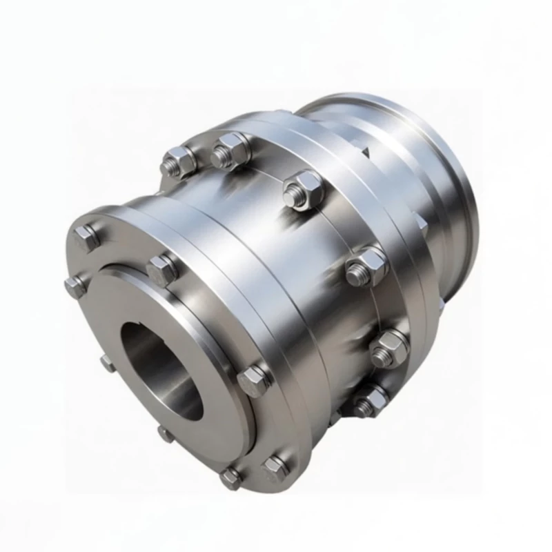
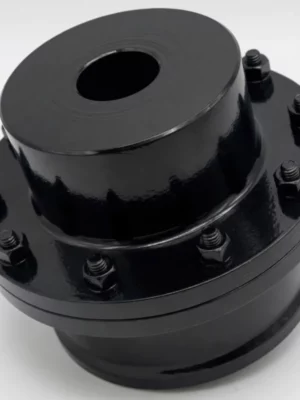
The WGC Drum Shape Gear Coupling is purpose-built for vertical shaft installations per JB/T7002-93, with a modified internal oil retention design that prevents lubrication starvation in both shaft-up and shaft-down orientations. Available in 14 sizes from 710 N·m to 160,000 N·m at up to 7500 RPM in Type I and Type II construction, it is the correct coupling for vertical turbine pumps, agitators, fans, and mixer drives where standard horizontal couplings fail from upper mesh lubricant starvation.
The only WG-family coupling purpose-built for vertical shaft drives. Modified internal oil retention keeps the crowned tooth mesh lubricated in both shaft-up and shaft-down orientations.
Torque Range
710 – 160,000 N·m
Max Speed
Up to 7500 RPM
Sizes
14 (WGC1–WGC14)
Standard
JB/T7002-93
Installation
Vertical Shaft
Types
Type I & Type II
Product Overview
The WGC drum shape gear coupling is the purpose-built vertical installation variant of the WG coupling family. It is the correct coupling to specify whenever a drivetrain is oriented vertically — whether shaft-up (motor above, driven machine below) or shaft-down (driven machine above, motor below) — and a standard horizontal gear coupling would fail from lubricant starvation at the upper tooth mesh within months of commissioning.
The WGC's core engineering difference from the WG base series is its internal oil retention design. On a horizontal shaft, gravity distributes lubricant naturally around the full tooth mesh circumference. On a vertical shaft, gravity pulls lubricant away from the upper mesh, starving it of the oil film it needs. The WGC addresses this with modified internal sleeve geometry and sealing that retains lubricant at both upper and lower meshes throughout operation, regardless of shaft orientation.
Technical Definition and Working Principle
Why Vertical Installation Requires a Dedicated Coupling
A standard WG coupling installed on a vertical shaft will initially operate correctly as the tooth mesh is lubricated at startup. Within the first 200–500 operating hours, however, the upper tooth mesh begins to run dry. The lubricant pools at the lower half under gravity, leaving the upper teeth in metal-to-metal contact. The result is rapid tooth wear, elevated vibration, and premature failure — often attributed incorrectly to misalignment, when the actual cause is wrong coupling selection for the installation orientation.
The WGC solves this with a modified internal geometry that produces an oil trap around both upper and lower tooth meshes. The outer sleeve profile and inner sealing arrangement work together to maintain lubricant film coverage at both meshes throughout operation — a fundamentally different approach to the sleeve cross-section and lubricant fill specification compared to the horizontal WG.
Crowned Tooth Geometry and Misalignment on Vertical Drives
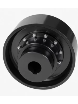
The WGC retains the same crowned tooth geometry as all WG-family couplings. Each hub carries externally crowned (barrel-shaped) teeth that mesh with internal straight teeth in the outer sleeve. The crown radius produces a self-centring Hertzian contact ellipse that remains near the centre of the tooth regardless of shaft misalignment, eliminating the destructive edge loading found in straight-tooth couplings under the same conditions.
On vertical drives, angular misalignment arises from different sources than on horizontal drives. Vertical turbine pump drives experience thermal expansion of the motor frame relative to the pump casing during heat-soak. Vertical agitator drives in heated vessels experience differential thermal growth between the vessel structure and the motor mounting frame. The WGC's 1.0–1.5 degree angular misalignment tolerance per mesh continuously absorbs these thermal misalignment events without tooth edge loading or bearing overloading.
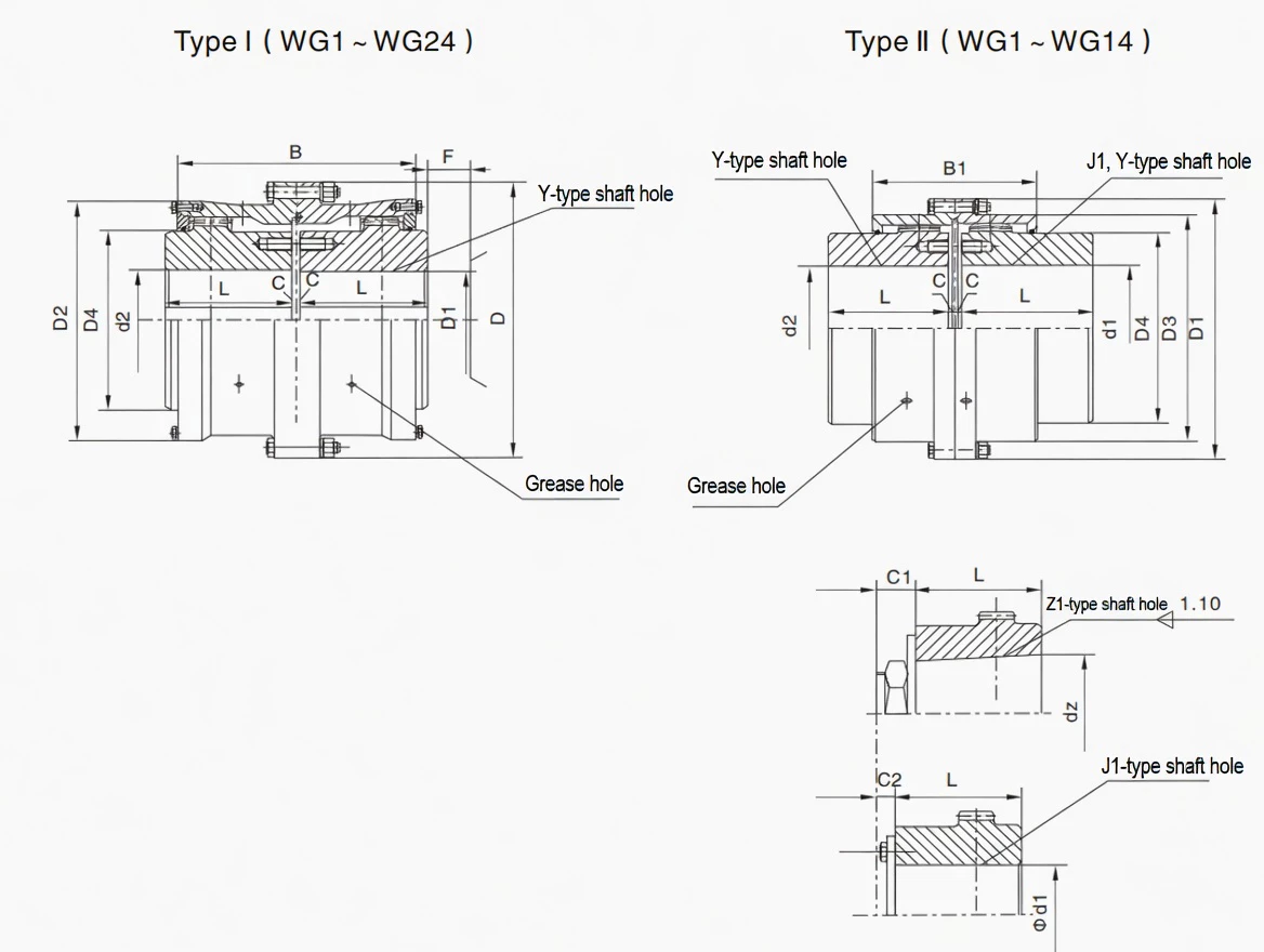
Type I and Type II Construction for Vertical Applications
The WGC is available in two construction types for WGC1 through WGC14. Type I uses a single outer sleeve design with vertical oil retention features built in. Type II adds an inner bore collar (D3 dimension) providing greater hub engagement length — preferred for applications where the drive experiences significant axial loading, such as vertical pump drives where hydraulic thrust passes through the coupling during priming.
Comparison with Other Coupling Types on Vertical Drives
Feature
WGC (this product)
WG (horizontal)
Jaw Coupling
Disc Coupling
Vertical Installation Rating
Purpose designed — JB/T7002-93
Not rated for vertical use
Yes — no lubrication needed
Yes — no lubrication needed
Oil Retention on Vertical Shaft
Modified geometry — both meshes retained
Upper mesh starved by gravity
N/A — elastomer element
N/A — no lubricant
Angular Misalignment Tolerance
1.0–1.5 deg per mesh
1.0–1.5 deg per mesh
Up to 1 deg
Up to 1 deg
Axial Displacement
Yes — shaft float absorbed
Yes
Limited
Yes
Shock Load Tolerance
Excellent — crowned teeth
Excellent
Good (elastomer dampens)
Poor — disc fatigue
Torque Capacity
710 – 160,000 N·m
710 – 1,250,000 N·m
Low–Medium
Medium
WGC in the WG Family — When Vertical Orientation Changes Everything
The WGC is the only member of the WG coupling family rated for vertical shaft installation. All five WG-family variants share the same crowned gear mesh principle; what makes the WGC unique is its internal modification for vertical lubricant retention.
Factor
WG
WGP
WGC
WGZ
WGT
Standard
JB/T8854.2
JB/T7001
JB/T7002-93
JB/T7003-93
JB/T7004
Shaft Orientation
Horizontal
Horizontal
Vertical — purpose built
Horizontal
Horizontal
Vertical Oil Retention
No
No
Yes — both meshes retained
No
No
Braking Feature
None
Flat disc — caliper
None
Drum — shoe brake
None
Intermediate Shaft
No
No
No
No
Yes
Sizes Available
24
14
14
14
24
Choose When...
Standard horizontal drive, no brake
Caliper disc brake required
Vertical shaft drive — pump, agitator, fan, mixer
Shoe brake required on horizontal drive
Distant shafts, axle withdrawal needed
Specifications & Size Matrix — WGC1 to WGC14
All specifications are from the WGC catalogue per JB/T7002-93. Dimensions in millimetres. Weight and inertia are calculated based on maximum shaft hole diameter, Y type bore. The B dimension is the Type I face width; B1 is the additional hub engagement length for Type II.
WGC1 – WGC14 Complete Specifications
Size
Torque (N·m)
Speed (rpm)
Bore d1,d2 (mm)
Y bore length
D
D1
D2
D4
B
B1
F
Inertia I (Kg·m²)
Inertia II (Kg·m²)
Weight I (Kg)
Weight II (Kg)
WGC1
710
7500
12 – 42
32–112
122
115
98
60
116
100
30
0.0079
0.0064
5.8
5.1
WGC2
1250
6700
22 – 56
52–112
150
145
118
77
136
104
30
0.022
0.017
7.9
—
WGC3
2500
6300
22 – 63
52–142
STEP 1
Incoming Material & Chemistry Check
STEP 2
CNC Hobbing, Bore & Oil Retention Machining
STEP 3
Carburising & Quench Hardening
STEP 4
CMM Inspection, Tooth Profile & Hardness
STEP 5
Lube Port Fitting, Vertical Fill Check & Pack
Certifications
ISO 9001:2015 quality management certification covers all WGC manufacturing operations. CE marking applies to applicable sizes. Products manufactured per JB/T7002-93. Every shipment includes material mill certificates, heat treatment records, Rockwell hardness test certificates, and dimensional inspection reports.
Why Source Your WGC Couplings from RP?
English-Speaking Engineering Team
Our engineers communicate in technical English and understand the engineering terminology. We can review vertical turbine pump data sheets, agitator drive specifications, and cooling tower fan drive drawings, and verify coupling selection with the specific data points engineers need.
Single-Unit Orders to Full Project Supply
WGC couplings are available from a single unit for emergency replacement through to full project quantities. Standard sizes ship within 15–20 working days ex-works; custom bores add 5–10 working days. Contact us for a quote.
Full WG Family — All Variants, One Supplier
As the manufacturer of WG, WGP, WGC, WGZ, and WGT, RP supplies the complete family from a single source. Processing plants requiring WGC on vertical agitator drives and WG on horizontal conveyor drives handle both through one engineering team and one procurement channel.
OEM and Custom Vertical Drive Solutions
Application Case Studies
Customer Profile: A mid-tier gold producer operating 18 vertical turbine dewatering pumps in open pit and underground configurations.
Challenge: The existing couplings on 12 of the 18 pumps were standard horizontal WG-type couplings installed by a local supplier who did not differentiate between horizontal and vertical ratings. These couplings were failing every 4–6 months due to upper mesh lubrication starvation, accounting for more than 60 hours of unplanned pump downtime per year across the 12 affected drives.
Solution: We supplied 12× WGC5 couplings (7,100 N·m, 75 mm bore, Type I) for the 18 kW and 22 kW pump drives, and 6× WGC7 (14,000 N·m, 95 mm bore, Type II) for the 37 kW and 45 kW deep-well pumps where higher axial thrust from the longer shaft column required the additional hub engagement of Type II.
Result: In 30 months of operation following replacement, zero coupling failures were recorded across all 18 drives. The mine's maintenance planner extended the coupling inspection interval from 4 months to 12 months based on observed wear at the first inspection. Estimated annual savings from eliminated unplanned downtime: USD $142,000.
Customer Profile: A metropolitan water authority operating eight vertical high-service pumps at a major water treatment facility, each rated 315 kW on continuous duty.
Challenge: The authority's asset management system required coupling replacement on 6 of the 8 pumps at 18-month intervals due to tooth wear. The chief engineer needed a coupling solution that would extend the 18-month replacement cycle to at least 5 years to meet new asset management KPIs.
Solution: We supplied 8× WGC10 couplings (40,000 N·m, 130 mm bore, Type I) with full material traceability documentation. The selection was validated against the pump's axial thrust data sheet and the motor-to-pump coupling distance.
Result: At the 24-month inspection, no measurable tooth wear was detected on any of the 8 couplings. The authority revised their maintenance plan to a 5-year inspection interval for WGC couplings on these drives, meeting the asset management KPI.
Case 3: Mineral Processing Vertical Leach Tank Agitators — Queensland
Customer Profile: A copper hydrometallurgical processing plant operating 24 vertical agitator drives on atmospheric leach tanks, each rated 55 kW continuous duty at 60–80°C process temperature.
Challenge: The plant was experiencing accelerated coupling wear on the agitator drives. Investigation identified two contributing factors: horizontal-rated couplings unsuitable for vertical orientation, and thermal growth of the heated tank structure pushing the lower agitator shaft upward by 1.8–2.2 mm during operation.
Solution: We supplied 24× WGC8 couplings (20,000 N·m, 95 mm bore, Type II) with Type II construction for additional axial loading resistance, lubricated with high-temperature EP grease rated to 180°C.
Result: The plant completed a full 12-month production campaign without a single coupling-related stoppage across all 24 agitator drives — compared to an average of 7 coupling replacements per campaign previously. Maintenance cost per campaign for coupling-related work reduced by USD $63,000.
Frequently Asked Questions
What is a WGC vertical installation drum shape gear coupling?
The WGC (JB/T7002-93) is a crowned-tooth gear coupling purpose-engineered for vertical shaft installations. Its internal construction maintains lubricant at both upper and lower tooth meshes in vertical orientation — eliminating the lubrication starvation failure that occurs when standard horizontal couplings are incorrectly used on vertical drives. 14 sizes cover 710 N·m to 160,000 N·m and up to 7500 RPM.
Why can't a standard horizontal gear coupling be used on a vertical shaft?
In a standard horizontal gear coupling, gravity distributes lubricant around the full tooth mesh circumference. In a vertical installation, gravity pulls lubricant to the lower half of the coupling, starving the upper tooth mesh of the oil film it needs — causing accelerated tooth wear, typically leading to coupling failure within 200–500 hours. The WGC's modified internal geometry retains lubricant at both meshes regardless of shaft orientation, eliminating this failure mode.
When should I choose WGC Type II over Type I?
Choose Type II when the vertical drive experiences significant axial loading — such as vertical turbine pump drives with hydraulic shaft thrust during priming, agitator drives in heated vessels with thermal axial growth, or drives with frequent reversals. Type I is lighter and suited to standard vertical drives with modest axial loads.
How is the WGC different from the WGP or WGZ?
The WGP and WGZ have no braking feature — they have flat disc and cylindrical drum braking surfaces respectively, and are designed for horizontal drives. The WGC has no braking feature — its unique modification is the internal vertical oil retention geometry. If you need a vertical drive with braking, contact our engineering team to discuss the correct solution.
What lubricant should be used in a WGC coupling?
EP-grade gear oil (ISO VG 220 or equivalent) or lithium complex grease with EP additives is standard for most WGC applications. For elevated-temperature environments (above 60°C ambient), a high-temperature EP grease rated to at least 150°C is recommended. The WGC must be filled to the specified volume for vertical installation — typically higher than the equivalent horizontal coupling fill level — to compensate for gravity effects on lubricant distribution within the oil trap geometry.
Can the WGC accommodate shaft float on vertical turbine pumps?
Yes. Shaft float during pump priming is accommodated by the axial sliding of the WGC's crowned teeth within the outer sleeve. The axial clearance in the coupling absorbs the shaft float without transmitting it as an axial thrust event to the motor bearing.
Specify Your WGC Coupling for Vertical Drive
Send us your motor power, speed, shaft bore diameter, and installation orientation. If you have axial thrust data or thermal growth estimates, include those too. Our engineering team confirms the right WGC size and construction type, and provides a factory-direct quotation within 24 hours.
Stainless steel gearboxes are widely used in industrial transmission fields due to their high strength and corrosion resistance. However, in actual use, stainless steel gearboxes may still malfunction due to improper design, installation, lubrication or maintenance....
In modern logistics automation systems, the CC600 Crate Conveyor Chain in Amsterdam plays a crucial role. With the continuous development of warehousing and sorting technologies, enterprises have increasingly higher requirements for the stability, efficiency and...
This article mainly explains and analyzes the structural design characteristics of the sprocket based on its role in the scraper conveyor, thereby leading to the necessity of researching the material and processing technology of the sprocket and the key technical...