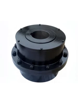
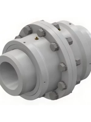
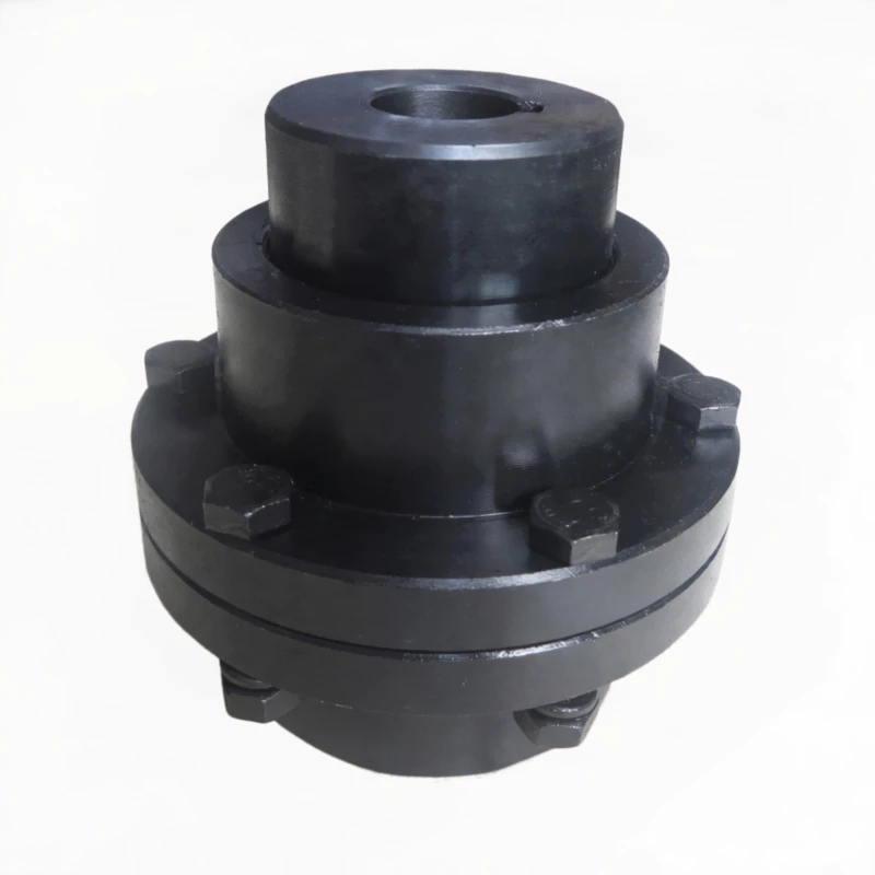
GCLD Drum Shape Gear Coupling — Motor Shaft Type
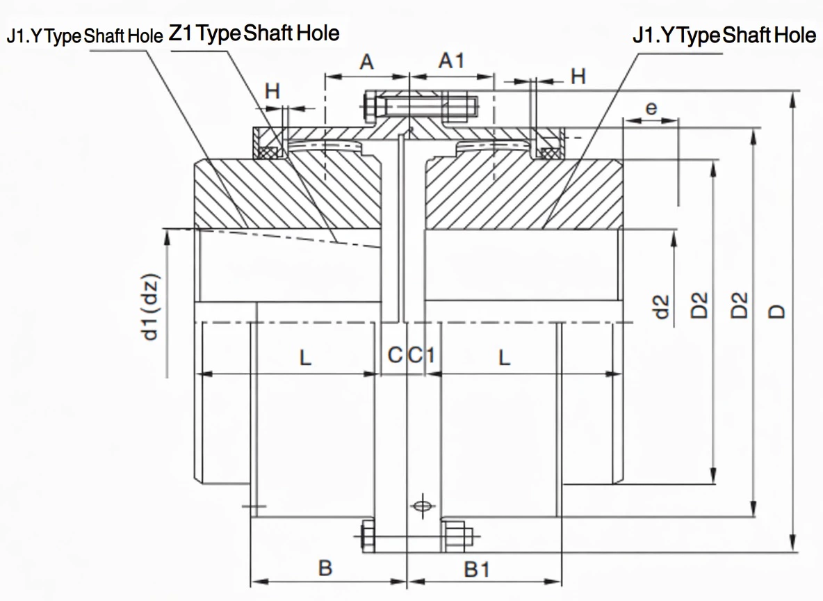
Crowned-tooth gear coupling engineered for direct motor shaft connections. Accepts cylindrical (J1/Y) and conical (Z1 taper) shaft ends.
Torque Range
1.12 – 50 KN·m
Speed Rating
Up to 4000 RPM
Sizes Available
10 (GCLD1–10)
Outer Dia. Range
127 – 362 mm
Product Overview
The GCLD drum shape gear coupling is a motor-dedicated crowned-tooth gear coupling manufactured to JB/T8854.1. It is the standard solution for connecting electric motor shaft ends directly to pumps, fans, agitators, compressors, and similar driven equipment — where a compact, high-torque, misalignment-tolerant coupling is required at the motor output.
This makes the GCLD the preferred choice whenever an engineer needs a compact, high-torque, misalignment-tolerant connection at the motor output shaft — without requiring a separate adaptor hub or intermediate shaft.
Technical Definition and Working Principle
What Defines the GCLD?
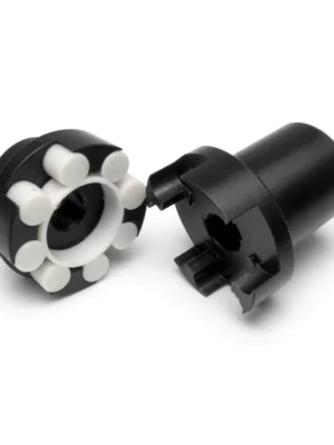
The GCLD is a single-pair crowned-tooth gear coupling consisting of two main components: an inner hub with external barrel-shaped (crowned) teeth, and an outer sleeve with internal straight teeth. The hub mounts on the motor shaft; the sleeve connects to the driven equipment.
The "drum shape" (crowned tooth) designation differentiates this coupling from a straight-tooth gear coupling. In a straight-tooth design, all tooth contact runs along a straight line across the tooth width — when shaft misalignment is present, this contact shifts to the tooth edge, creating concentrated stress that accelerates tooth wear and can cause tooth breakage under shock loads.
How the Crowned Tooth Geometry Works
Each external tooth on the GCLD hub is machined with a spherical crown radius in the tooth width direction. When shaft misalignment is present, the external crowned tooth rotates within the internal sleeve tooth space, with contact rolling toward the centre of the tooth width — maintaining a near-Hertzian contact patch regardless of angular offset up to the rated misalignment limit.
- Angular misalignment — typically 1.0 to 1.5 degrees, compensating for motor-to-gearbox angular offset caused by foundation movement, thermal growth, or imprecise installation.
- Radial (parallel) misalignment — limited lateral displacement between motor and driven shaft centrelines.
- Axial displacement — the teeth slide axially within the sleeve as the motor shaft extends thermally during operation, preventing thrust loads from being transmitted to motor bearings.
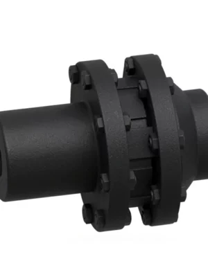
The Z1 conical bore variant adds a further benefit: the taper fit produces a self-centring, key-free connection that is highly resistant to fretting and micro-slip under reversing torque loads — making it particularly well suited for fan drives and process equipment with frequent start-stop cycling.
GCLD vs. Other Coupling Types — Quick Comparison
| Feature |
GCLD Drum Gear |
Jaw Coupling |
Disc Coupling |
Rigid Flange |
| Conical (Z1) Shaft Support |
Yes (standard option) |
Limited |
No |
No |
| Angular Misalignment |
1.0–1.5 deg per mesh |
Up to 1 deg |
Up to 1 deg |
Near zero |
| Torque Capacity (this size range) |
1.12–50 KN·m |
Low–Medium |
Medium |
High |
| Shock Load Tolerance |
Excellent |
Good (elastomer) |
Poor |
Transmitted fully |
| Axial Displacement |
Yes (built-in) |
Limited |
Yes |
No |
| High-Speed Suitability |
Up to 4000 RPM |
Moderate |
High |
High |
| Lubrication Required |
Yes (6–12 months) |
No |
No |
No |
Specifications & Size Matrix — GCLD1 to GCLD10
All specifications below are extracted directly from the GCLD product catalogue per JB/T8854.1 standard. Dimensions in millimetres. The GCLD series spans 10 sizes covering torques from 1.12 KN·m (GCLD1) to 50 KN·m (GCLD10).
GCLD1 – GCLD5 Specifications
| Type |
Torque
(KN·m) |
Speed
(R/min) |
Shaft Bore
D1, d2, dz (mm) |
Y |
J1, Z1 |
D |
D1 |
D2 |
C |
C1 |
H |
B |
B1 |
e |
Inertia
(Kg·m²) |
Weight
(Kg) |
| GCLD1 |
1.12 |
4000 |
22, 24 |
52 |
38 |
127 |
95 |
75 |
27 |
6 |
2 |
66 |
45 |
42 |
0.00875 |
6.2 |
| 25, 28 |
62 |
44 |
0.01025 |
7.2 |
| 30, 32, 35, 38 |
82 |
60 |
0.011 |
7.8 |
| 40, 42, 45, 48, 50, 55, 56 |
112 |
84 |
0.01175 |
9.6 |
| GCLD2 |
1.8 |
4000 |
38 |
82 |
60 |
149 |
116 |
90 |
26.5 |
6.5 |
2 |
70 |
49 |
42 |
0.02125 |
11.2 |
| 40, 42, 45, 48, 50, 55, 56 |
112 |
84 |
33 |
0.02425 |
14 |
| 60, 63, 65 |
142 |
107 |
33 |
0.0215 |
16.4 |
| GCLD3 |
3.15 |
4000 |
40, 42, 45, 48, 50, 55, 56 |
112 |
84 |
167 |
134 |
105 |
33 |
7 |
2.5 |
80 |
54 |
42 |
0.04 |
17.2 |
| 60, 63, 65, 70, 71, 75 |
142 |
107 |
0.0475 |
22.4 |
| GCLD4 |
5 |
4000 |
45, 48, 50, 55, 56 |
112 |
84 |
187 |
153 |
125 |
33.5 |
7.5 |
2.5 |
81 |
55 |
42 |
0.0725 |
25.2 |
| 60, 63, 65, 70, 71, 75 |
142 |
107 |
38 |
0.0825 |
26.4 |
| 80, 85, 90 |
172 |
132 |
38 |
0.095 |
35.6 |
| GCLD5 |
7.1 |
3750 |
50, 55 |
112 |
84 |
204 |
170 |
140 |
37.5 |
7.5 |
2.5 |
89 |
59 |
42 |
0.1125 |
31.6 |
| 60, 63, 65, 70, 71, 75 |
142 |
107 |
37.5 |
0.1275 |
38 |
| 80, 85, 90, 95 |
172 |
132 |
43.5 |
0.145 |
44.6 |
| 100 (105) |
212 |
167 |
43.5 |
0.1675 |
53.9 |
GCLD6 – GCLD10 Specifications
| Type |
Torque
(KN·m) |
Speed
(R/min) |
Shaft Bore
D1, d2, dz (mm) |
Y |
J1, Z1 |
D |
D1 |
D2 |
C |
C1 |
H |
B |
B1 |
e |
Inertia
(Kg·m²) |
Weight
(Kg) |
| GCLD6 |
10 |
3300 |
(50) 56 |
112 |
84 |
230 |
186 |
155 |
43.5 |
8.5 |
3 |
106 |
71 |
47 |
0.1875 |
40.5 |
| 60, 63, 65, 70, 71, 75 |
142 |
107 |
0.21 |
49.8 |
| 80, 85, 90, 95 |
172 |
132 |
0.235 |
56.3 |
| 100, 110 (115) |
212 |
167 |
0.2675 |
67.5 |
| GCLD7 |
16 |
3000 |
60, 63, 65, 70, 71, 75 |
142 |
107 |
256 |
212 |
180 |
48 |
9 |
3 |
112 |
73 |
47 |
0.3575 |
63.9 |
| 80, 85, 90, 95 |
172 |
132 |
0.40 |
74.7 |
| 100, 110, 120, 125 |
212 |
167 |
0.4625 |
88 |
| 130, 135 |
252 |
202 |
0.5275 |
106.7 |
| GCLD8 |
22.4 |
2650 |
65, 70, 71, 75 |
142 |
107 |
287 |
239 |
200 |
40.5 |
8.5 |
3.5 |
118 |
82 |
47 |
0.560 |
81.7 |
| 80, 85, 90, 95 |
172 |
132 |
40.5 |
0.6275 |
95.5 |
| 100, 110, 120, 125 |
212 |
167 |
48 |
0.72 |
114 |
| 130, 140, 150 |
252 |
202 |
48 |
0.8125 |
123 |
| GCLD9 |
35.5 |
2350 |
70, 71, 75 |
142 |
107 |
325 |
276 |
235 |
49.5 |
9.5 |
3.5 |
132 |
85 |
47 |
1.0775 |
112 |
| 80, 85, 90, 95 |
172 |
132 |
49.5 |
1.2075 |
130 |
| 100, 110, 120, 125 |
212 |
167 |
58 |
1.3825 |
156 |
| 130, 140, 150 |
252 |
202 |
58 |
1.56 |
181 |
| 160, 170 (175) |
302 |
242 |
58 |
1.77 |
212 |
| GCLD10 |
50 |
2100 |
75 |
142 |
107 |
362 |
313 |
270 |
65 |
11 |
4 |
149 |
95 |
49 |
1.97 |
161 |
| 80, 85, 90, 95 |
172 |
132 |
65 |
2.0725 |
172 |
| 100, 110, 120, 125 |
212 |
167 |
65 |
2.38 |
206 |
| 130, 140, 150 |
252 |
202 |
68 |
2.5625 |
239 |
| 160, 170, 180 |
302 |
242 |
68 |
3.055 |
280 |
| 190, 200 |
352 |
282 |
68 |
3.4255 |
319 |
Note: Shaft hole diameters in parentheses are not recommended for new designs. Shaft hole length for J1 type is recommended. Y type bore length is shorter.
Custom Bore & Shaft Fit Available
Need a Z1 taper bore, a non-standard keyway, or a special shaft fit tolerance? Our team machines to your drawing within 5–10 working days. Send your shaft drawing here for a fast response.
Technical Advantages — Why Drum Shape Outperforms Straight Tooth
The performance difference between a drum shape gear coupling and a straight-tooth gear coupling is not merely a matter of degree — it is a fundamental difference in how contact stress is managed under misalignment.
Higher Misalignment Tolerance
The GCLD's crowned tooth profile produces a self-centring Hertzian contact that remains near the tooth centre regardless of shaft angle. This allows the coupling to operate continuously at its rated angular misalignment (typically 1.0–1.5°) without edge loading — which is the root cause of straight-tooth coupling failures in misaligned applications.
Longer Service Life Under Shock Loads
When a crusher ingests tramp iron, or a pump starts against a closed discharge valve, torque spikes of 2–4× nominal occur instantaneously. A straight-tooth coupling concentrates these spikes on the tooth edge when misaligned — the crowned profile distributes them over a larger contact area, greatly reducing the risk of tooth breakage.
Reduced Bearing Loads
A misaligned straight-tooth coupling generates bending moments and cyclic radial forces that are transmitted directly into the motor's drive-end bearing. At 2× running frequency, these forces can accelerate bearing fatigue. The GCLD's crowned tooth self-centres under load, generating lower radial force transmission to connected bearings.
Lower Maintenance Frequency
Because the crowned tooth generates less heat and lower vibration under misalignment, the GCLD enables closer coupling of motor to driven equipment, reduces heat input to the motor bearing housing, and allows operation in environments where coupling misalignment cannot be fully controlled.
Suitable for High-Speed Applications
The smaller GCLD sizes (GCLD1 through GCLD4) are rated to 4000 RPM — suitable for direct motor coupling on standard IEC 4-pole machines and on some 2-pole 50 Hz applications. The crowned tooth profile is particularly important at high speeds, where even small misalignment generates significant centrifugal load distribution effects.
Manufacturing & Quality Assurance
Manufacturing Process Highlights
Every GCLD coupling begins as a forged alloy steel blank — typically 42CrMo4 for sizes GCLD6 and above, and 45# carbon steel for smaller sizes. The crowned tooth profiles are generated on CNC gear hobbing machines and verified using dedicated gear measurement equipment to verify profile accuracy.
Bores are finish-machined after heat treatment using CNC turning centres with live tooling for keyways. Z1 conical bores are machined and gauged with dedicated taper gauges to verify taper ratio and contact pattern before dispatch.
Quality Control Flow
STEP 1
Incoming Material Inspection & Mill Certificate
STEP 2
Rough Turning & CNC Gear Hobbing
STEP 3
Heat Treatment (Carburising + Quenching)
STEP 4
CMM Inspection, Tooth Profile & Hardness Test
STEP 5
Assembly, Painting & Export Packing
Inspection Equipment
Our quality laboratory is equipped with CNC gear profile testers for verifying crowned tooth geometry and tooth pitch, and Rockwell hardness testers for post-quench hardness verification.
Certifications
ISO 9001:2015 quality management system certification covers the full GCLD manufacturing process from raw material receipt through to finished goods despatch. CE marking applies to applicable coupling sizes.
Why Source Your GCLD Couplings from RP?
15+ Years Export Experience
English-Speaking Engineering Team
Our technical team communicates in engineering English. We review your coupling selection calculations, check load factors, verify bore and keyway specifications, and provide installation guidance — not just a catalogue number.
Flexible MOQ
We supply from a single piece. Volume pricing is applied automatically for orders of 10 or more units of the same part number.
OEM & Custom Capability
Beyond the standard catalogue, we manufacture to customer drawings. Non-standard Z1 taper ratios, special keyway profiles, extended hub lengths, and modified bore configurations are available.
Factory Direct — No Markups
Application Case Studies
Case 1: Dewatering Pump Motor Drive — Queensland Coal Mine
Challenge: Pump motors (132 kW, IEC 315 frame, cylindrical shaft end) were experiencing coupling failures every 9–12 months due to foundation settlement across an expanding mine site causing misalignment that exceeded the coupling's rated tolerance.
Solution: We supplied 28x GCLD7 couplings (16 KN·m, 100 mm bore, J1 type) across all pump stations. The GCLD7's 1.0–1.5 degree angular tolerance was confirmed to exceed the worst-case foundation settlement misalignment measured on site.
Result: After two full wet seasons (24 months), no coupling failures were recorded. The site maintenance coordinator confirmed that coupling-related call-outs to pump stations had ceased entirely.
Customer Profile: A 500 MW coal-fired power station operating four forced-draft fans, each driven by a 400 kW IEC motor with Z1 conical shaft end.
Challenge: Existing disc couplings were failing every 14–16 months due to disc pack fatigue caused by combined angular and axial misalignment. The motor's conical shaft required an adaptor hub with the previous coupling design, adding complexity and a potential failure point.
Solution: We supplied 4x GCLD9 couplings (35.5 KN·m, 110 mm Z1 taper bore) that mount directly onto the motor conical shaft — eliminating the adaptor hub. The Z1 taper connection provides a more rigid, fretting-resistant joint than the previous keyed cylindrical arrangement.
Result: Fan drives have operated for 28 months without coupling replacement or scheduled intervention. Elimination of the adaptor hub reduced assembly time during the original installation.
Customer Profile: A copper concentrator operating a flotation cell drive system with six 75 kW motors.
Challenge: Motor-to-gearbox couplings were causing recurring motor bearing failures every 10 months. Vibration analysis identified the source as coupling-induced 2× RPM forcing from a straight-tooth gear coupling operating under residual misalignment.
Solution: We supplied 6x GCLD6 couplings (10 KN·m, 75 mm bore, Y type) as direct replacements. Pre-installation alignment checks confirmed residual misalignment of 0.4–0.7 degrees — within the GCLD6's rated tolerance.
Result: The 2× RPM vibration signature disappeared from all six drives within two weeks of installation. After 20 months, no motor bearing replacements have been required.
Frequently Asked Questions
What is a GCLD drum shape gear coupling?
The GCLD is a crowned-tooth gear coupling designed specifically for electric motor shaft connections. It conforms to JB/T8854.1 and covers 10 sizes from GCLD1 (1.12 KN·m) to GCLD10 (50 KN·m).
What shaft types does the GCLD coupling accept?
The GCLD accepts Y type (cylindrical shaft with keyway), J1 type (cylindrical shaft with keyway, longer engagement length), and Z1 type (conical taper shaft) on the motor side. The driven-equipment side uses a standard cylindrical bore.
What is the difference between GCLD and GIICL gear couplings?
The GCLD is motor-specific and supports Z1 conical taper bores alongside cylindrical bores. The GIICL is a general-purpose crowned-tooth coupling for shaft-to-shaft connections, supporting only cylindrical bores. choose GCLD when connecting directly to an electric motor shaft.
Can you supply custom bore sizes for GCLD couplings?
Yes. All GCLD sizes are available with custom bore machining including Y, J1, and Z1 configurations. We machine to your shaft diameter, keyway dimensions, and tolerance class. For Z1 taper bores, please provide your taper ratio (or motor frame designation) and we will verify the taper angle and diameter.
What lubrication does a GCLD gear coupling require?
GCLD couplings require periodic lubrication with EP-grade gear oil or lithium complex grease rated for the ambient operating temperature. Standard re-lubrication intervals are every 6–12 months under normal industrial conditions, or every 3–6 months in high-temperature or contaminated environments.
What is the outer diameter and weight range of the GCLD series?
The GCLD outer diameter D ranges from 127 mm (GCLD1) to 362 mm (GCLD10). Weight ranges from 6.2 kg (GCLD1, smallest bore) to 319 kg (GCLD10, largest bore). Rotational inertia spans from 0.0025 kg·m² (GCLD1) to 3.12 kg·m² (GCLD10).
Need a GCLD Coupling for Your Motor Drive?
Send us your motor shaft dimensions, frame size, or coupling drawing. Our engineering team confirms the correct GCLD size and bore configuration — and provides a competitive, factory-direct quotation within one business day.
Reply within 24 hours
|
English-speaking engineering team
|
sales@netherlandsdrive.com
RP — Factory-direct GCLD drum shape gear couplings for global industrial customers.