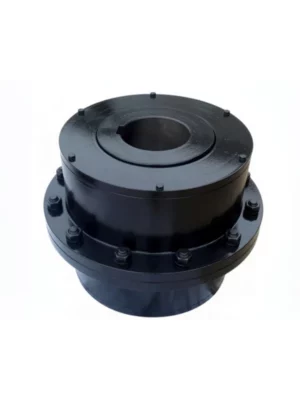
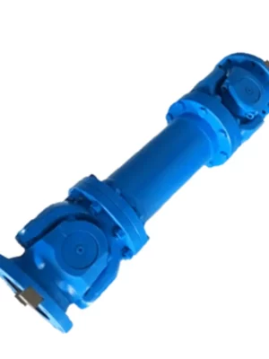
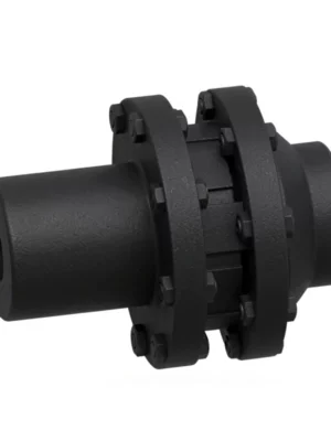
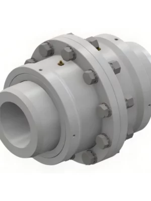
GIICLZ Drum Shape Gear Coupling — Intermediate Shaft Type
High-torque, crowned-tooth gear coupling with intermediate shaft for heavy-duty power transmission across widely spaced shafts.
Torque Range
0.4 – 4500 KN·m
Speed Rating
Up to 4000 RPM
Sizes Available
25 (GIICLZ1–25)
Outer Dia. Range
103 – 1644 mm
Weight Range
3.3 – 27797 Kg
Product Overview
The GIICLZ drum shape gear coupling is a moveable rigid coupling engineered for connecting two shafts positioned at a significant distance apart. It incorporates an intermediate shaft (spacer tube) between two crowned-tooth gear meshes, allowing it to span the gap between motor and driven equipment without requiring additional bearing supports.
What Is a GIICLZ Drum Shape Gear Coupling?
Technical Definition
A drum shape gear coupling — also called a crowned tooth gear coupling — is a type of rigid-flexible coupling where the external gear teeth on each hub are machined with a convex (barrel-shaped) profile across the tooth width. This crowned geometry allows the coupling to accommodate angular misalignment between the connected shafts while maintaining full torque transmission capacity.
This crowned tooth geometry is the critical differentiator from a straight-tooth gear coupling. Where a straight-tooth coupling transmits torque through a line contact that becomes edge-loaded under misalignment, the crowned profile maintains a near-central Hertzian contact patch regardless of angular offset — distributing load more evenly and extending tooth life significantly.
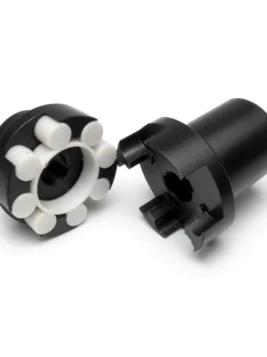
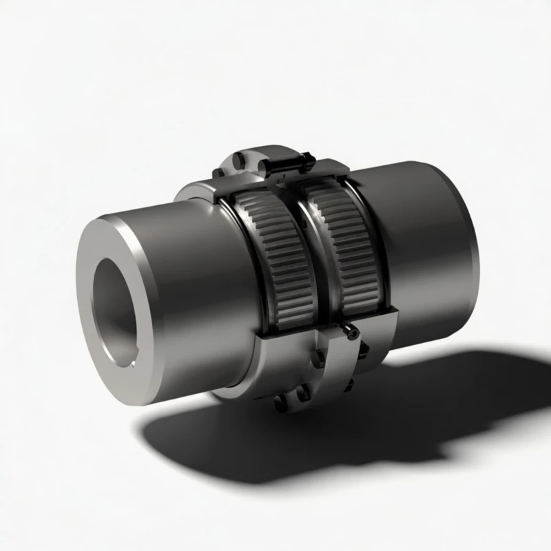
Working Principle
The GIICLZ consists of two outer sleeves (each with internal straight teeth), two inner hubs (each with external crowned teeth), and a tubular intermediate shaft connecting the two hub-sleeve assemblies. Torque is transmitted from one shaft through hub 1 → sleeve 1 → intermediate shaft → sleeve 2 → hub 2 to the second shaft.
The crowned tooth profile allows each mesh to accommodate angular misalignment of typically 1.0 to 1.5 degrees per mesh. Because the GIICLZ has two meshes, the total angular compensation capacity of the assembly reaches up to 3 degrees — useful for correcting shaft misalignment in both the vertical and horizontal planes simultaneously.
The barrel shape of the teeth also permits axial sliding within the tooth mesh as shafts expand thermally or shift under load, providing built-in axial displacement compensation without generating significant restoring forces on the connected shaft bearings.
Comparison with Other Coupling Types
| Feature |
GIICLZ Drum Gear |
Jaw Coupling |
Disc Coupling |
Grid Coupling |
| Max Torque Capacity |
Very High (to 4500 KN·m) |
Low-Medium |
Medium |
Medium-High |
| Angular Misalignment |
1.0-1.5 deg per mesh |
Up to 1 deg |
Up to 1 deg |
Up to 0.33 deg |
| Axial Displacement |
Yes (built-in) |
Limited |
Yes |
Yes |
| Shock Load Tolerance |
Excellent |
Good (elastomer absorbs) |
Poor |
Good |
| High-Speed Suitability |
Up to 4000 RPM |
Moderate |
High |
Moderate |
| Lubrication Required |
Yes |
No |
No |
Yes |
| Intermediate Shaft Option |
Standard (Z type) |
No |
Yes (spacer) |
Yes (spacer) |
| Typical Application Scale |
Heavy industrial |
Light-medium duty |
Precision drives |
Medium-heavy duty |
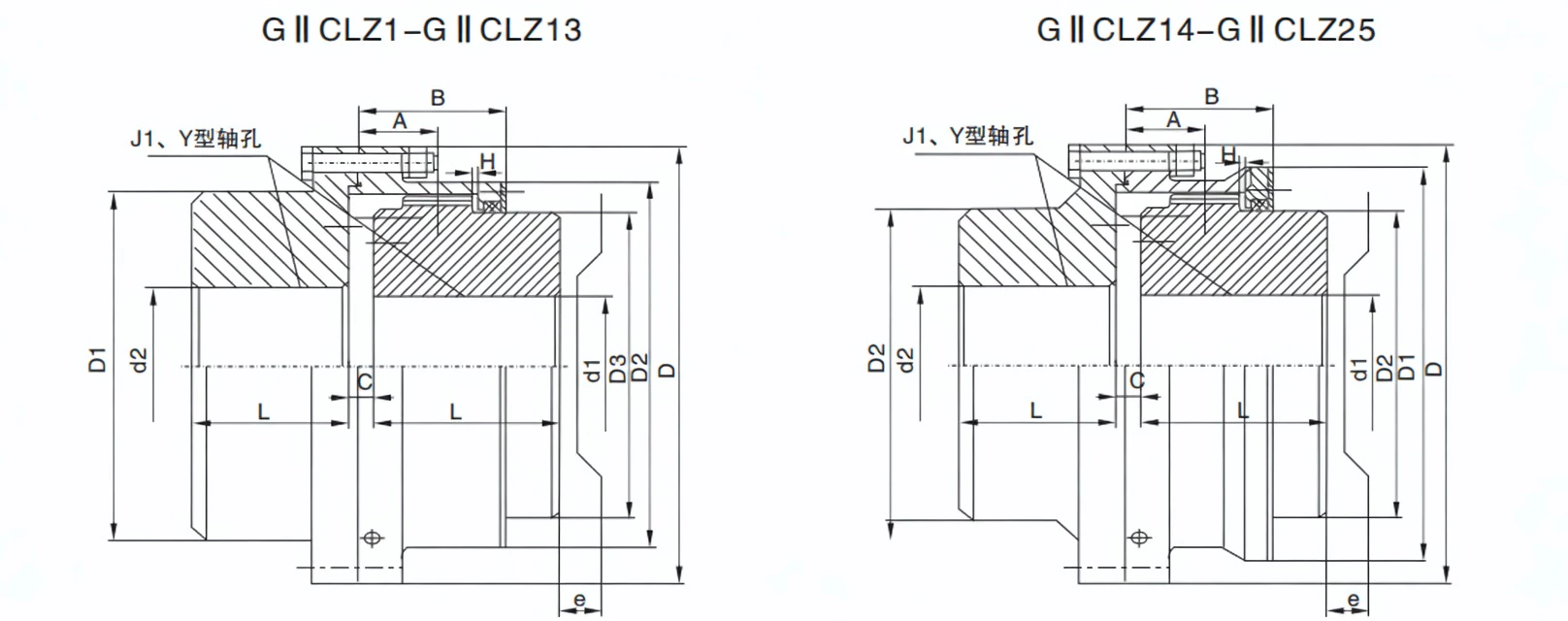
Specifications & Size Matrix — GIICLZ1 to GIICLZ25
The following dimensional tables are extracted directly from our product catalogue based on JB/T8854.2 and JB/T8854.3 standards. All dimensions are in millimetres. The GIICLZ series covers 25 sizes from GIICLZ1 through GIICLZ25.
GIICLZ1 – GIICLZ9 Specifications
| Type |
Torque
(KN·m) |
Speed
(R/min) |
Shaft Bore d1, d2 |
Y |
J1 |
D |
D1 |
D2 |
D3 |
C |
H |
A |
B |
e |
Inertia
(Kg·m²) |
Weight
(Kg) |
| GIICLZ1 |
0.4 |
4000 |
16,18,19 |
42 |
– |
103 |
71 |
71 |
50 |
8 |
2 |
18 |
38 |
38 |
0.004 |
3.5 |
| 20,22,24 |
52 |
38 |
0.00375 |
3.3 |
| 25,28 |
62 |
44 |
0.004 |
3.5 |
| 30,32,35,38* |
82 |
60 |
0.005 |
4.1 |
| 40*,42*,45*,48*,50* |
112 |
84 |
0.007 |
5.7 |
| GIICLZ2 |
0.71 |
4000 |
20,22,24 |
52 |
– |
115 |
83 |
83 |
60 |
8 |
2 |
21 |
44 |
42 |
0.00675 |
5.3 |
| 25,28 |
62 |
44 |
0.00625 |
4.8 |
| 30,32,35,38 |
82 |
60 |
0.007 |
5.7 |
| 40,42,45,48,50*,55*,56* |
112 |
84 |
0.008 |
7.2 |
| GIICLZ3 |
1.12 |
4000 |
22,24 – 38 |
52–82 |
–/44/60 |
127 |
95 |
95 |
75 |
8 |
2 |
22 |
45 |
42 |
0.009–0.011 |
3.8–7.8 |
| 40–56, 60*,63*,65*,70* |
112–142 |
84/107 |
0.01325–0.01675 |
9.8–12.5 |
| GIICLZ4 |
1.8 |
4000 |
38 – 55,56 |
82–112 |
60/84 |
149 |
116 |
116 |
90 |
8 |
2 |
24.5 |
49 |
42 |
0.02125–0.0255 |
10.5–13.5 |
| 60–75*, 80* |
142–172 |
107/132 |
0.039–0.04875 |
16.5–19.4 |
| GIICLZ5 |
3.15 |
4000 |
40–90* |
112–172 |
84–132 |
167 |
134 |
134 |
105 |
10 |
2.5 |
27.5 |
54 |
42 |
0.044–0.0625 |
18.1–28.5 |
| GIICLZ6 |
5.00 |
4000 |
45–105* |
112–212 |
84–167 |
187 |
153 |
153 |
125 |
10 |
2.5 |
28 |
55 |
42 |
0.075–0.1065 |
23.9–36.2 |
| GIICLZ7 |
7.1 |
3750 |
50–115* |
112–212 |
84–167 |
204 |
170 |
170 |
140 |
10 |
2.5 |
30 |
59 |
42 |
0.1145–0.1898 |
29.6–54.3 |
| GIICLZ8 |
10.0 |
3300 |
55–125* |
112–212 |
84–167 |
230 |
186 |
186 |
155 |
12 |
3 |
33.5 |
71 |
47 |
0.184–0.297 |
37.8–67.4 |
| GIICLZ9 |
16.0 |
3000 |
60–150* |
142–252 |
107–202 |
256 |
222 |
212 |
180 |
12 |
3 |
34.5 |
73 |
47 |
0.358–0.575 |
60–104.4 |
GIICLZ10 – GIICLZ25 Specifications
| Type |
Torque
(KN·m) |
Speed
(R/min) |
Shaft Bore d1, d2 |
Y |
L |
D |
D1 |
D2 |
D3 |
C |
H |
A |
B |
e |
Inertia
(Kg·m²) |
Weight
(Kg) |
| GIICLZ10 |
22.4 |
2650 |
65–150 |
142–252 |
107–202 |
287 |
239 |
239 |
200 |
14 |
3.5 |
39 |
82 |
47 |
0.58–0.935 |
76.1–133 |
| GIICLZ11 |
35.5 |
2350 |
110–200 |
212–352 |
167–282 |
325 |
250 |
276 |
235 |
14 |
3.5 |
40.5 |
85 |
47 |
1.223–1.625 |
137–193 |
| GIICLZ12 |
50 |
2100 |
130–200 |
252–352 |
202–282 |
362 |
286 |
313 |
270 |
16 |
4 |
44.5 |
95 |
49 |
2.39–3.093 |
212.8–290 |
| GIICLZ13 |
71 |
1850 |
150–225 |
252–352 |
202–282 |
412 |
322 |
350 |
300 |
18 |
4.5 |
49 |
104 |
49 |
3.93–6.34 |
272.3–370 |
| GIICLZ14 |
112 |
1650 |
170–250 |
302–410 |
242–330 |
462 |
420 |
335 |
– |
22 |
5.5 |
86 |
148 |
63 |
6.9–8.6 |
389–509 |
| GIICLZ15 |
180 |
1500 |
190–285 |
352–470 |
282–380 |
512 |
465 |
380 |
– |
22 |
5.5 |
91 |
158 |
63 |
12.425–15.575 |
566–740 |
| GIICLZ16 |
250 |
1300 |
220–320 |
352–470 |
282–380 |
580 |
522 |
430 |
– |
28 |
7 |
104.5 |
177 |
67 |
21.2–26.35 |
751–974 |
| GIICLZ17 |
355 |
1200 |
250–365 |
410–550 |
330–450 |
644 |
582 |
490 |
– |
28 |
7 |
99 |
182 |
67 |
38.825–49.5 |
1110–1465 |
| GIICLZ18 |
500 |
1050 |
280–400 |
470–650 |
380–540 |
726 |
658 |
540 |
– |
28 |
8 |
111 |
215 |
75 |
69.5–90.5 |
1580–2160 |
| GIICLZ19 |
710 |
950 |
300–470 |
470–650 |
380–540 |
818 |
748 |
630 |
– |
32 |
9 |
116 |
220 |
75 |
122.5–161.25 |
2115–2892 |
| GIICLZ20 |
1000 |
800 |
360–540 |
550–800 |
450–680 |
928 |
838 |
720 |
– |
32 |
10.5 |
123.5 |
235 |
75 |
240–335 |
3223–4680 |
| GIICLZ21 |
1400 |
750 |
400–600 |
650–800 |
540–680 |
1022 |
928 |
810 |
– |
40 |
11.5 |
127.5 |
245 |
75 |
435–527.75 |
4780–5905 |
| GIICLZ22 |
1800 |
650 |
450–680 |
650–900 |
540–780 |
1134 |
1036 |
915 |
– |
40 |
13 |
131 |
255 |
75 |
701.25–852.25 |
6069–7504 |
| GIICLZ23 |
2500 |
600 |
530–770 |
800–900 |
680–780 |
1282 |
1178 |
1030 |
– |
50 |
14.5 |
149.5 |
290 |
80 |
1415.75–1638.75 |
9633–11133 |
| GIICLZ24 |
3550 |
550 |
560–850 |
800–1000 |
680–880 |
1428 |
1322 |
1175 |
– |
50 |
16.5 |
158.5 |
305 |
80 |
2330.5–2976.25 |
12460–16110 |
| GIICLZ25 |
4500 |
460 |
670–1040 |
900–1000 |
780–1100 |
1644 |
1538 |
1390 |
– |
50 |
19 |
162.5 |
310 |
80 |
5174.25–7198.25 |
19837–27797 |
Note: Shaft hole lengths are recommended per J1 type. Bore diameters marked with an asterisk (*) are not recommended for new designs. Rotation inertia and weight are calculated based on J1 type minimum bore configuration.
Custom Bore & Shaft Fit Available
Need a non-standard bore, keyway, spline, or taper lock fit? Our engineering team machines custom shaft holes to your drawing within 3–5 working days. Send your drawing here.
GICL vs GICLZ vs GIICL vs GIICLZ — Gear Coupling Comparison
Selecting the right gear coupling variant depends on shaft spacing, required misalignment compensation, and whether an intermediate shaft is needed. Here is a clear side-by-side comparison to guide your selection.
| Feature |
GICL |
GICLZ |
GIICL |
GIICLZ |
| Standard |
JB/T8854.3 |
JB/T8854.3 |
JB/T8854.2 |
JB/T8854.2 & .3 |
| Tooth Meshes |
1 pair drum teeth |
1 pair drum teeth |
2 pairs drum teeth |
2 pairs drum teeth |
| Intermediate Shaft |
No |
Yes |
No |
Yes |
| Misalignment Compensation |
Moderate |
Higher (spacer adds range) |
High (two meshes) |
Highest (two meshes + spacer) |
| Shaft Spacing |
Close-coupled |
Extended distance |
Close-coupled |
Extended distance |
| Structure Compactness |
Most compact |
Moderate |
Compact |
Longest overall |
| Typical Use |
Standard drives, small inertia |
Long-span drives |
High misalignment, compact |
Heavy-duty, long span, high misalignment |
| Recommended For |
General machinery |
Pump sets, fan drives |
Rolling mills, compressors |
Mining, steel, cement, power gen |
Technical Advantages — Why Drum Shape Beats Straight Tooth
The fundamental difference between a drum shape (crowned) gear coupling and a straight-tooth gear coupling lies in the tooth contact geometry. A straight-tooth coupling transmits torque through a line contact running the full tooth width — when angular misalignment is present, the contact shifts to the tooth edge, creating concentrated stress.
Higher Misalignment Tolerance
Each crowned tooth mesh in the GIICLZ can accommodate angular misalignment of 1.0 to 1.5 degrees. With two meshes, the total system tolerance reaches up to 3 degrees. Straight-tooth couplings typically allow only 0.5 degrees or less before edge loading occurs.
Longer Service Life Under Shock Loads
The contact stress in a crowned tooth mesh is distributed as a Hertzian ellipse rather than a concentrated edge line. This means maximum surface stress is significantly lower for a given torque and misalignment combination — translating directly to longer tooth and coupling service life.
Reduced Bearing Loads
When a straight-tooth coupling operates under misalignment, it generates cyclic radial forces at twice the rotational frequency. These forces are transmitted directly into the shaft bearings and can cause premature bearing failure, particularly when the coupling is close to the motor drive-end bearing.
Lower Maintenance Frequency
Suitable for High-Speed Applications
The GIICLZ series supports speeds up to 4000 RPM for smaller sizes (GIICLZ1–GIICLZ6). The crowned tooth profile generates less heat at speed because it avoids the scrubbing action of edge-loaded straight teeth under misalignment.
Manufacturing & Quality Assurance
Process Highlights
Every GIICLZ coupling is produced in our ISO 9001:2015 certified facility using forged alloy steel blanks (typically 42CrMo or 45# carbon steel, depending on size and torque requirement). The crowned tooth profiles are generated on CNC gear hobbing machines and verified using dedicated gear measurement equipment.
Quality Control Flow
STEP 1
Incoming Material Inspection & Certification
STEP 2
CNC Machining & Gear Hobbing
STEP 3
Heat Treatment (Carburising + Quenching)
STEP 4
CMM Inspection & Tooth Profile Check
STEP 5
Assembly, Painting & Packing
Inspection Equipment
Our quality laboratory is equipped with: CNC gear profile testers for verifying crowned tooth geometry, Rockwell hardness testers for post-heat-treatment verification, and calibrated CMM equipment for dimensional inspection.
Certifications & Standards Compliance
ISO 9001:2015 quality management system certification. CE marking for applicable coupling sizes.
Why Source Your GIICLZ Gear Couplings from RP?
English-Speaking Engineering Team
Our technical support team includes mechanical engineers who communicate in English. From initial coupling selection and sizing through to installation guidance and troubleshooting support, we provide direct technical assistance throughout the product lifecycle.
Competitive MOQ for SME Buyers
OEM & Custom Capability
Beyond standard catalogue sizes, we manufacture to customer drawings. Custom bore sizes, special keyway profiles, non-standard intermediate shaft lengths, and modified flange drilling patterns are all available.
Factory Direct Pricing
As a manufacturer — not a trading company — RP offers factory pricing with full traceability. Every coupling ships with material certificates, hardness reports, and dimensional inspection records.
Application Case Studies
Customer Profile: A mid-tier iron ore producer operating a 3.2 km overland conveyor system.
Challenge: The existing straight-tooth gear couplings on the head drive were failing every 8–10 months due to foundation settlement causing misalignment exceeding the coupling's rated tolerance. Each failure resulted in 16–24 hours of conveyor downtime.
Solution: We supplied 2x GIICLZ14 couplings (112 KN·m rated torque, 220 mm bore) with custom intermediate shaft lengths of 450 mm to match the existing drivetrain layout. Bores were machined to customer-supplied shaft drawings with fitted keyways.
Result: After 30 months in service, no coupling failures have been recorded. The estimated annual saving in avoided downtime and replacement costs exceeds USD $80,000. Bearing vibration levels on the head drive gearbox reduced by 40% following installation.
Case 2: Cement Mill Main Drive — Queensland
Customer Profile: A major cement manufacturer operating a 4.2 m diameter ball mill.
Challenge: The mill's 1800 kW drive experiences significant thermal expansion during operation, causing the motor shaft to extend axially by up to 2 mm. The previous disc coupling was transmitting axial growth as a bearing load, resulting in premature motor bearing failure every 14 months.
Solution: We supplied a GIICLZ18 coupling (500 KN·m rated torque, 340 mm bore) with a 600 mm intermediate shaft. The crowned tooth design inherently accommodates axial displacement without generating restoring forces — eliminating the root cause of the motor bearing failures.
Result: Motor bearing service life extended to 36+ months (a 157% improvement). The coupling has operated for 24 months with no maintenance intervention other than scheduled re-lubrication.
Case 3: Steel Rolling Mill — New South Wales
Customer Profile: An integrated steelworks operating a hot strip rolling mill with multiple drive stands.
Challenge: The roughing mill stand drive couplings were experiencing tooth breakage under the severe torque reversals that occur during each rolling pass. The plant was replacing couplings every 4–6 months.
Solution: We supplied 4x GIICLZ16 couplings (250 KN·m rated torque) with upgraded 42CrMo forgings and enhanced heat treatment for maximum shock resistance. Custom bore and keyway configurations matched the existing shaft arrangement.
Result: Service life increased from 4–6 months to 18+ months (a 3x improvement). Annual coupling-related maintenance budget for the roughing stand reduced by approximately USD $75,000.
Frequently Asked Questions
What is a GIICLZ drum shape gear coupling?
The GIICLZ is a moveable rigid coupling that uses crowned (barrel-shaped) tooth geometry on two external gear hubs connected via an intermediate shaft sleeve with internal straight teeth. It compensates for angular misalignment (up to ±1.5° per mesh, ±3° total), axial displacement, and limited radial offset through the tooth mesh geometry.
What is the difference between GIICLZ and GIICL couplings?
The GIICLZ includes an intermediate shaft (spacer) between the two coupling halves, enabling connection of shafts spaced further apart. The GIICL is a close-coupled version without the intermediate shaft.
What torque range does the GIICLZ series cover?
The GIICLZ series spans 25 sizes covering a torque range from 0.4 KN·m (GIICLZ1) up to 4500 KN·m (GIICLZ25). This range addresses everything from small conveyor drives and agitator connections through to primary mill drives and large industrial gearbox outputs.
Can you supply custom bore sizes for GIICLZ couplings?
Yes. We offer custom bore machining including keyway, spline, and taper bore configurations. Each GIICLZ size supports a defined range of shaft hole diameters (refer to the specification table). For bores outside the standard range or non-standard keyway profiles, please contact us with your shaft drawing.
What maintenance does a GIICLZ coupling require?
GIICLZ couplings require periodic lubrication (typically every 6–12 months depending on operating conditions), seal inspection, and visual checks for tooth wear. The drum-shaped tooth geometry is self-centering and wear-tolerant, meaning that minor tooth surface marks do not indicate immediate replacement — a worn coupling continues to function safely until the tooth profile measurement indicates replacement is due.
Ready to Specify Your GIICLZ Coupling?
Send us your shaft dimensions, torque requirements, or equipment drawing. Our engineering team will verify the correct GIICLZ size and provide a competitive quotation — typically within one business day.
Reply within 24 hours
|
Engineer-to-engineer support
|
sales@netherlandsdrive.com