


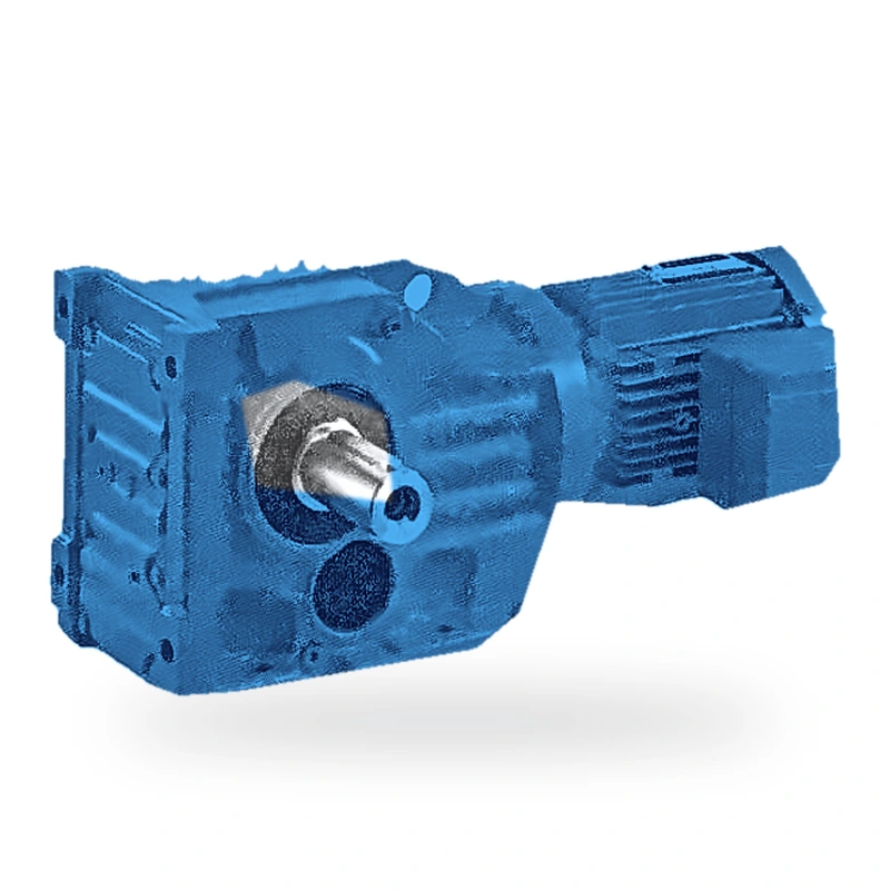
EP-K57 Right-Angle Helical Bevel Gear Reducer
Input Power 0.12–7.5 kW | Max. Output Torque 1100 N·m | Gear Ratio 5.36–145 | Right-Angle Output • Multiple Mounting Types
Product Overview
The EP-K57 is a helical-bevel gear reducer designed for industrial applications that require a
right-angle (90°) change of transmission direction. The drive combines
two stages of helical cylindrical gears with one stage of spiral bevel gears
in a compact three-stage arrangement, delivering precise directional change, wide ratio coverage,
and high efficiency in a single robust housing.
All gears are machined from 20CrMnTi low-carbon alloy steel, carburised and case-hardened to a
tooth-flank hardness of HRC 58–62, with contact fatigue strength σH ≥ 1,500 MPa and bending
fatigue strength σF ≥ 450 MPa. Ground tooth flanks achieve GB/T 10095.1 accuracy grade 6,
minimising noise and vibration and maximising transmission smoothness.
The EP-K57 covers an input power range of 0.12–7.5 kW and a maximum permitted
output torque of 1100 N·m. The standard gear ratio range is 5.36–145,
giving output speeds from 9.9–445 rpm with a 4P / 6P induction or servo motor.
Six mounting types — foot (K), B5-flange (KF), shaft-mounted hollow-bore (KA, KAF),
GK-housing hollow-bore (KAB), and torque-arm shaft-mounted (KAT) — cover virtually
every installation requirement. Standard ingress protection is IP55, with IP65 available on request.
The housing is precision-cast from HT250 high-strength grey cast iron and stress-relief aged
to ensure long-term dimensional stability. All rolling-element bearings are sourced from
premium manufacturers, designed to an L10h service life of ≥ 20,000 hours.
A balanced internal pressure system and high-integrity shaft seals prevent lubricant leakage
and exclude external contamination.
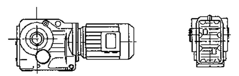

Key Technical Specifications
| Parameter | Value | Notes |
|---|---|---|
| Frame Size | 57 | K57 series |
| Rated Input Power | 0.12–7.5 kW | Mating motor power range |
| Max. Output Torque | 1100 N·m | Permitted maximum |
| Gear Ratio Range | 5.36–145 | Standard ratio series |
| Output Speed Range | 9.9–445 rpm | With standard motor speeds |
| Permitted Radial Force | 9,434 N | At output shaft end |
| Unit Weight | 29–39 kg | Varies with motor configuration |
| Mounting Positions | M1–M6 (6 positions) | Any mounting orientation |
| Motor Pole Count | 4P / 6P | Standard 50 Hz configuration |
| Gear Accuracy Grade | Grade 6 | GB/T 10095.1 |
| Ingress Protection | IP55 standard / IP65 optional | GB/T 4942.1 |
| Lubrication | Splash + pressure-balanced breather | Mineral oil standard |
| Ambient Temperature | −10 °C to +40 °C | Synthetic oil for low-temp. sites |
| Duty Cycle | Continuous (S1) | Intermittent duty also supported |
| Noise Level | ≤78 dB(A) | No-load, rated speed |
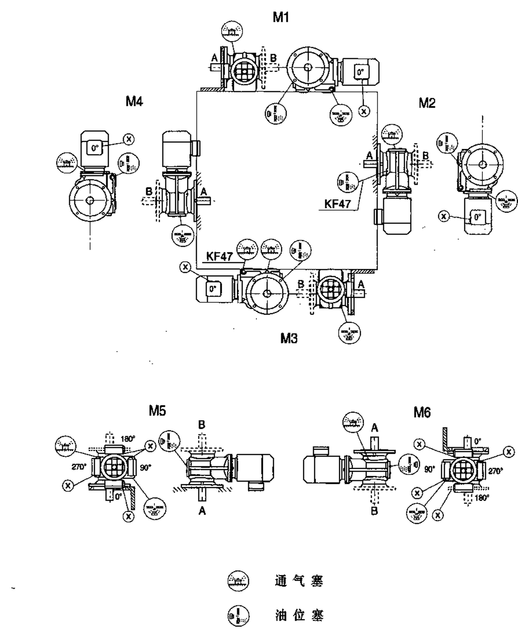
Mounting Types & Installation Positions
The EP-K57 is available in the following mounting configurations, each designed for a specific
installation requirement:
- K57 (foot-mounted, solid output shaft)
- KF57 (B5 flange-mounted, solid output shaft)
- KA57 (shaft-mounted, hollow output shaft)
- KAF57 (B5 flange + hollow output shaft)
- KAB57 (GK housing, hollow output shaft)
- KAB57 — GK-housing shaft-mount type with hollow output shaft; designed for high radial loads (available on selected sizes)
- K57SZ — input-shaft-only variant (no motor); accepts a customer-supplied coupling or pulley
- K57R — combination of K57 and R-series helical reducer for very high overall ratios
- KAT57 — KA type with integrated anti-rotation torque arm for rigid shaft-mount installations
All mounting types support six standard mounting positions (M1 to M6):
| Position | Definition | Typical Use |
|---|---|---|
| M1 | Motor horizontal, housing feet down (standard position) | Suits the majority of horizontal drive applications |
| M2 | Motor horizontal, motor below housing | For upward-facing output shaft or suspended installation |
| M3 | Motor horizontal, housing feet up | For overhead platform mounting |
| M4 | Motor above housing | Saves horizontal floor space in side-drive layouts |
| M5 | Motor horizontal, housing left side down | For drives mounted on a vertical face |
| M6 | Motor horizontal, housing right side down | Mirror image of M5 for opposite-hand mounting |

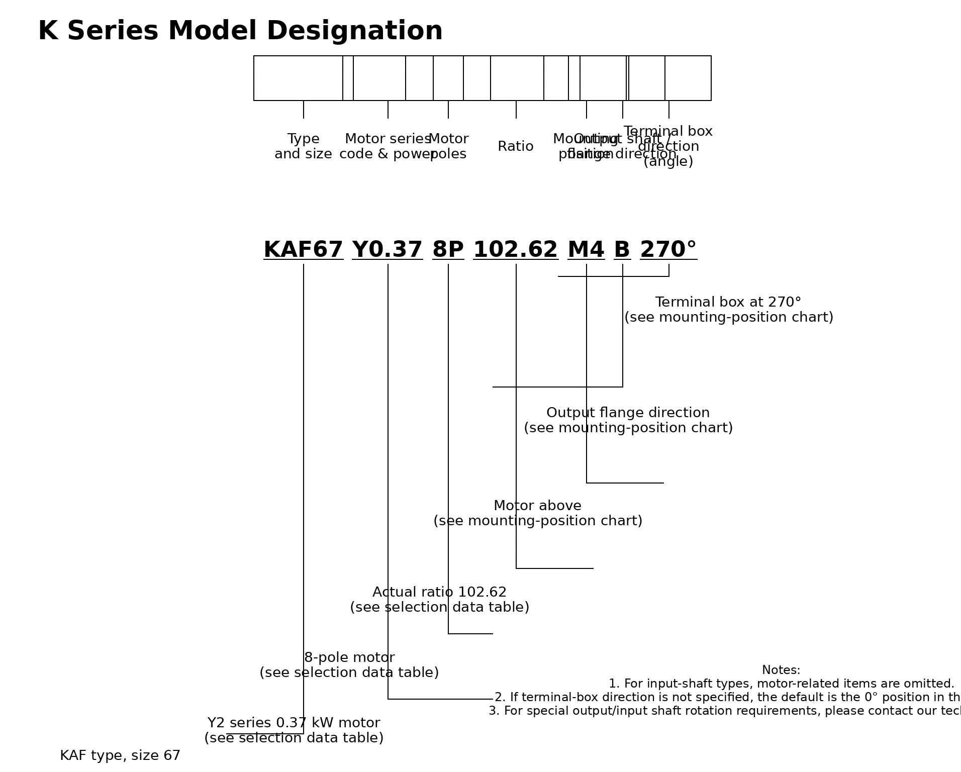
Model Designation Guide
A complete EP-K57 series model number encodes all key configuration data.
The fields are defined in the table below:
| Field | Example | Meaning |
|---|---|---|
| Mounting type | KAF | B5-flange + hollow output shaft |
| Frame size | 57 | Housing size number |
| Motor type & power | Y0.75 | Y-series motor, 0.75 kW |
| Pole count | 4P | 4-pole motor (approx. 1,450 rpm) |
| Gear ratio | 35.57 | Exact ratio from standard series |
| Mounting position | M1 | Standard horizontal, feet down |
| Output shaft direction | B | Output shaft hand (A or B) |
| Terminal box position | 90° | Motor terminal box orientation |
Order example: KAF57-Y0.75-4P-35.57-M1-B-90°
— KAF-type, frame 57, Y-series 0.75 kW motor, 4-pole, ratio 35.57, M1 mounting, B-hand output, terminal box at 90°.

Typical Industry Applications
| Industry | Typical Application |
|---|---|
| Chemical Processing | Metering pumps and slow-speed agitator drives in reaction vessels. |
| Building Materials | Kiln roller hearths and hydraulic press slow-feed drives. |
| Water Treatment | Aerators, sludge scrapers, and continuous-duty mixing equipment. |
| Extruder feed screws and internal mixer auxiliary drives. |
The 90° right-angle output shaft of the EP-K57 gives it a decisive advantage wherever
space is constrained or the transmission direction must change. From precision low-speed
processes to continuous heavy-duty industrial operations, the EP-K57
delivers a reliable and efficient drive solution across a wide range of sectors.
Case Study: Municipal Wastewater Aeration
Key Product Advantages
Three-stage combined drive achieves 94–97% unit efficiency. Ground spiral bevel flanks minimise mesh losses and heat generation.
Compact housing achieves an excellent torque-to-weight ratio. The K57 frame delivers up to 1100 N·m in a package weighing only 29–39 kg.
L10h bearing life target ≥ 20,000 hours. Premium rolling bearings, engineered lubrication and robust sealing support a 15–20 year equipment life.
Foot, flange, shaft-mount and torque-arm types with M1–M6 positions cover virtually every spatial constraint and layout requirement.
Grade 6 ground gears and precision-balanced spiral bevel stage keep sound pressure below 78 dB(A), suitable for noise-sensitive production environments.
Standard ratio series 5.36–145 covers a broad output speed range in one frame size, eliminating the need for separate gearbox families for different applications.
Selection Guide
Confirm the following parameters before finalising your EP-K57 selection:
| Selection Criterion | Guidance | EP-K57 Limit |
|---|---|---|
| Required output torque | Calculate from load and duty cycle | ≤ 1100 N·m |
| Service factor fB | 1.0 smooth; 1.25–1.75 moderate shock | Apply to required torque before comparing |
| Required gear ratio | Motor speed ÷ output speed | Select nearest standard value in 5.36–145 |
| Motor input power | Rated motor power | Within 0.12–7.5 kW range |
| Mounting type | Match to equipment layout | K / KF / KA / KAF / KAB / KAT |
| Output radial force | Include belt/chain tension | ≤ 9,434 N |
About Ever Power
Ever Power is a specialist manufacturer and global supplier of industrial power transmission equipment,
including helical-bevel gear reducers, helical gear reducers, worm gear reducers, planetary gearboxes,
bevel gearboxes, and matched gearmotors. Our manufacturing facilities operate under ISO 9001 quality
management systems, and our products carry CE certification as standard.
With customers across mining, cement, steel, paper, port, food processing, and general industrial sectors,
Ever Power combines engineering depth with responsive global logistics. Our technical team provides
full selection calculations, dimensional drawings, and application engineering support —
typically within one working day.
We supply sample quantities of 1–5 units for evaluation and prototype projects.
Mixed-model orders are accepted from approximately USD 1,500. Standard production lead time is
10–25 working days; priority scheduling is available for urgent requirements.
Learn more about Ever Power.
Frequently Asked Questions
What does the ‘SZ' suffix mean in the K57 model designation?
Is the anti-rotation torque arm on a KAT57 standard or optional?
Can the K57 be combined with an R-series reducer?
What is the permitted radial load at the K57 output shaft?
Can the K57 run continuously for 24 hours at rated load?
Request a Quote or Technical Support
Need technical data sheets, CAD drawings, or a custom selection service for the EP-K57?
Our engineering team is ready to assist:
- Full selection parameter tables (constant-power and constant-torque duty)
- Free 2D and 3D installation dimension drawings
- Custom gear ratios, ingress protection levels, and surface treatments
- Samples: 1–5 units; mixed orders from approx. USD 1,500; 10–25 working days lead time