


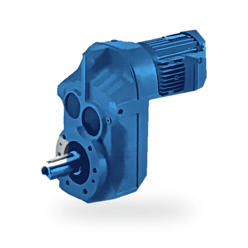
Product Overview — EP-F67 Parallel-Shaft Helical Gear Reducer
Chemical process engineers and environmental engineers share a common requirement: a drive unit that maintains stable, predictable torque delivery even when product viscosity, temperature, and batching cycles vary from hour to hour. The EP-F67 parallel-shaft helical gear reducer meets this standard through its two-stage precision-ground gear train, rated at up to 1,100 N·m continuous output torque across a power range of 0.12–11 kW and ratios of 3.77–59.14.
The parallel-shaft layout is particularly valued in shaft-mounted agitator configurations, where the gearbox sits at the top of the vessel and its hollow output bore slips directly over the agitator shaft. With no intervening coupling to align, installation is faster and the overall drive height above the vessel lid is reduced, easing access for vessel maintenance. Our application support team can advise on shaft-seal selection for pressurised or vacuum-rated vessels.
Viton lip seals and ATEX-compliant variants are available for hazardous-area operation. The housing paint system is compatible with common chemical splashes; stainless fasteners and corrosion-inhibited primer are selectable for aggressive environments.
Technical Specifications — EP-F67
| Parameter | Specification |
|---|---|
| Gear Type | Multi-stage parallel-shaft helical gears, precision-ground DIN 6/ISO 6 |
| Number of Stages | 2-stage |
| Motor Power Range | 0.12–11 kW |
| Max Output Torque | 1,100 N·m |
| Gear Ratio Range | 3.77–59.14 |
| Output Speed Range | 25–370 rpm |
| Approximate Unit Weight | 22–36 kg |
| Max Output Radial Load | 8,700 N |
| Transmission Efficiency | ≥ 96% per stage (overall ≥ 92% for 2-stage, ≥ 88% for 3-stage) |
| Lubrication | Splash lubrication; ISO VG 220 mineral oil (factory fill) |
| Housing Material | Close-grained cast iron (HT250 / EN-GJL-250) |
| Gear Material | Case-hardened alloy steel (20CrMnTi / 20MnCr5), HRC 58–62 |
| Protection Rating | IP55 standard; IP65 optional |
| Ambient Temperature | −25 °C to +45 °C (standard lubricant) |
| Noise Level | ≤ 72 dB(A) at rated load (1 m, free-field) |
| Standards Compliance | ISO 6336, DIN 3990 gear rating; ISO 281 bearing life; CE Machinery Directive |
Structural Types & Mounting Configurations — F67 Series
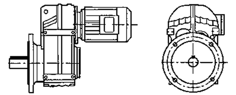
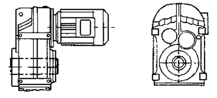
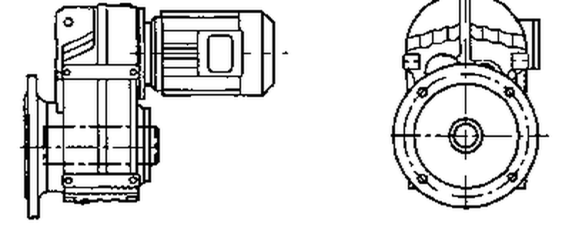
The F67 series is available in multiple structural types to suit different installation geometries and driven-machine interfaces. All types share the same internal gear set and achieve identical torque and efficiency ratings; the differences lie in mounting method and output connection.
| Type Code | Description |
|---|---|
| F67 | foot-mounted, solid output shaft |
| FF67 | B5 flange-mounted, solid output shaft |
| FA67 | shaft-mounted, hollow output shaft |
| FAF67 | B5 flange + hollow output shaft |
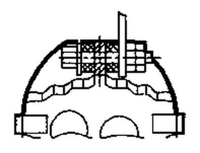
| FAT67 | torque-arm, hollow output shaft |

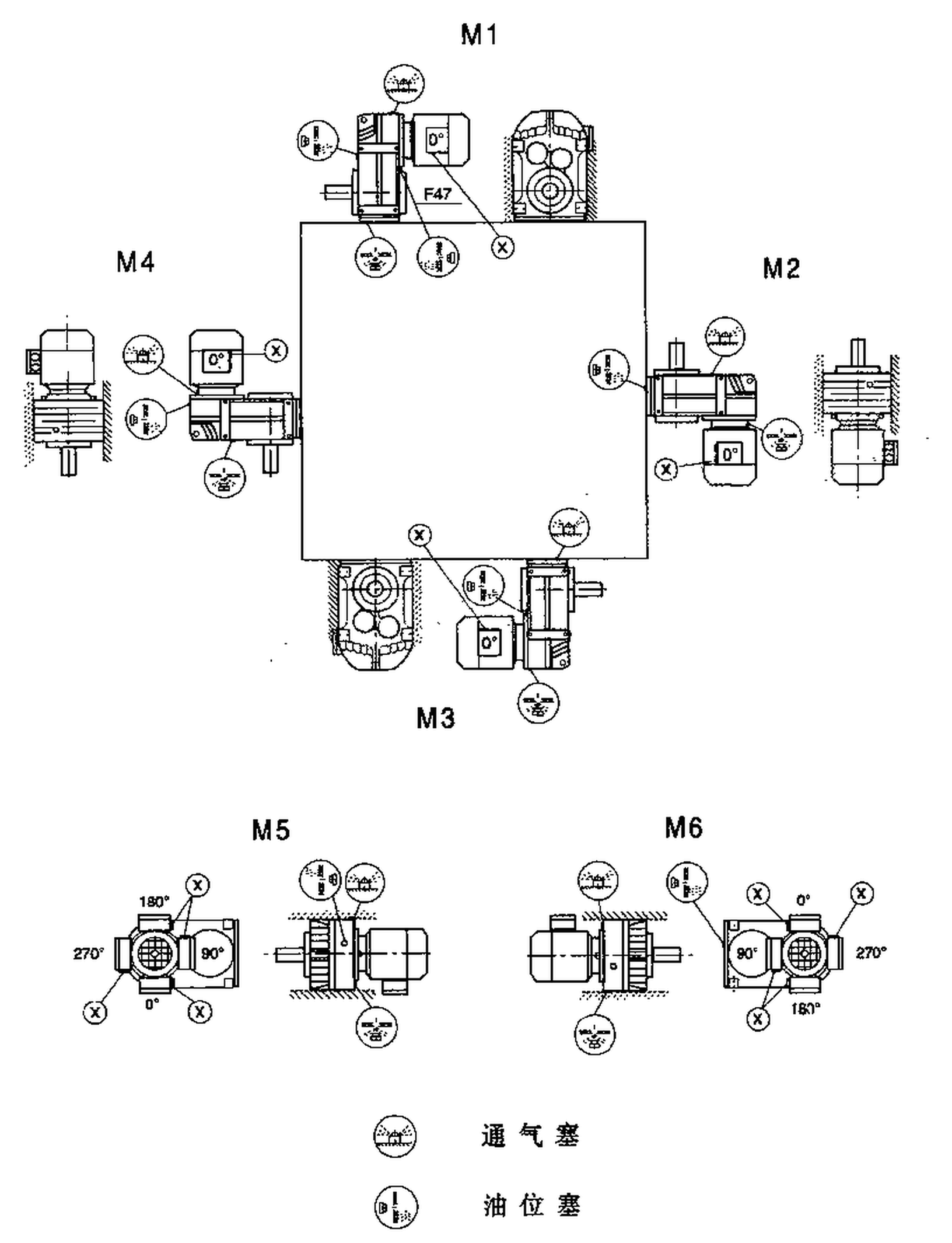
Mounting Positions M1–M6
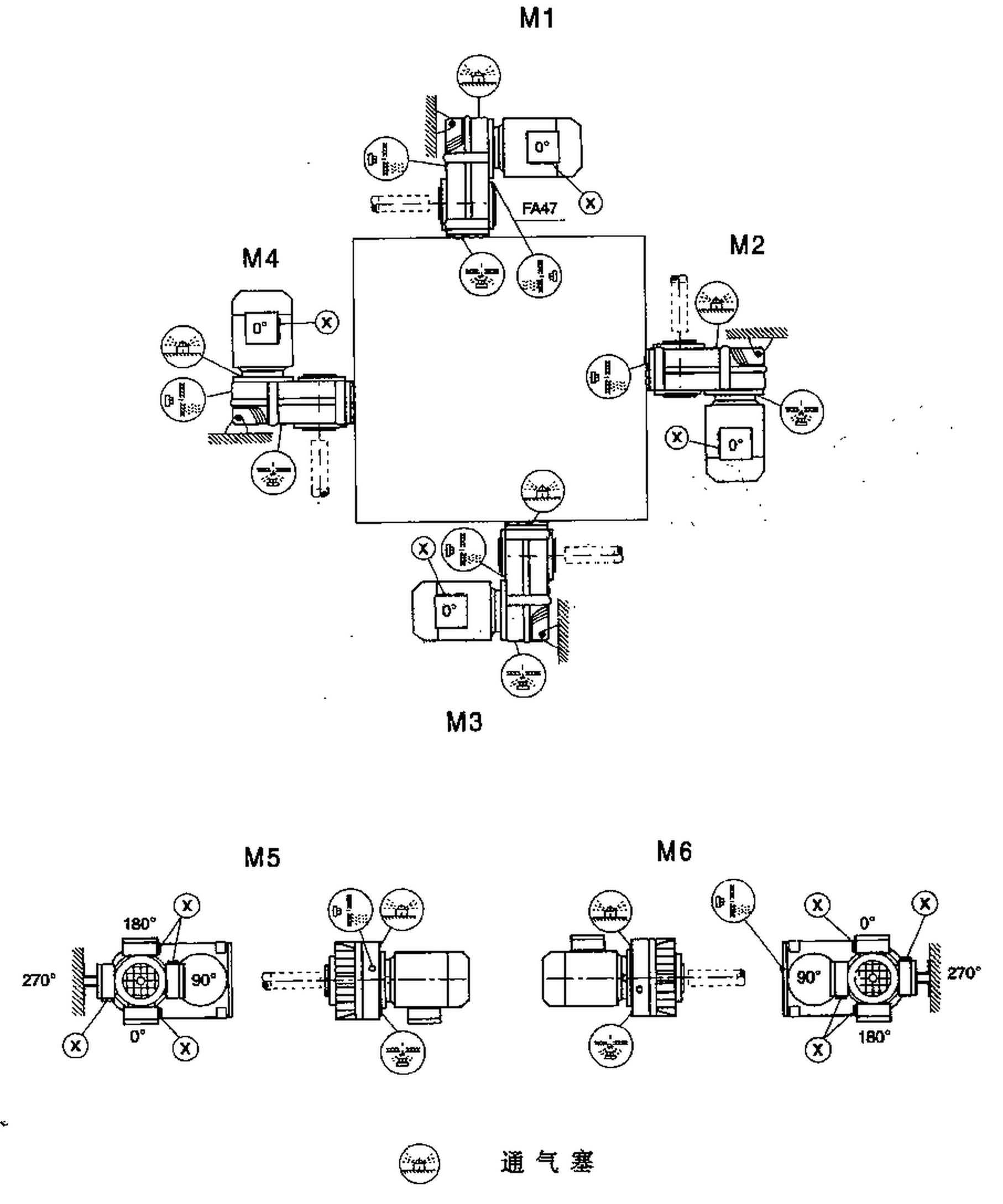
All F67 structural types support six standard mounting positions (M1 through M6), defined by the angular orientation of the output shaft relative to the horizontal. Oil fill level and vent plug position must be adjusted for each mounting position; refer to the installation manual for position-specific fill quantities and the correct vent-plug orientation.

Key Advantages of the EP-F67
Each gear stage delivers ≥96% mechanical efficiency through precision-ground helical flanks and optimised tooth profile corrections. Compared with worm reducers of equivalent output torque, the EP-F67 typically saves 15–35% in electrical energy over the same duty cycle — a saving that often exceeds the gearbox purchase price within two years.
With up to 1,100 N·m from a housing sized for 0.12–11 kW, the EP-F67 achieves torque density competitive with bevel-helical units of the same output-shaft diameter. The case-hardened alloy-steel gears (HRC 58–62) sustain high Hertzian contact stress without case fatigue, enabling compact dimensions even at the upper end of the power range.
Bearings are selected for a minimum L10h life of 20,000 hours at rated conditions and verified by ISO 281 calculation using actual application load spectra. Precision-ground gears eliminate the geometric errors that cause micro-pitting, extending tooth-flank life to typically 40,000 hours or more when correctly lubricated.
Five standard structural types — F, FF, FA, FAF, FAT — and an input-shaft-only FA-SZ variant address virtually every machine interface geometry without custom engineering. The FA and FAT hollow-bore types eliminate external couplings entirely, reducing drivetrain length and eliminating one routine maintenance item.
Helical gear engagement produces a progressive, distributed contact zone rather than the sudden full-face mesh of spur gears. This characteristic, combined with profile-ground tooth flanks and dynamically balanced rotating components, keeps noise levels below 72 dB(A) at 1 m — important in operator-occupied environments and buildings with vibration-sensitive equipment.
The parallel-shaft geometry keeps the overall drive envelope short in the radial direction, allowing direct-couple installation in machine frames where right-angle units would require a longer cantilevered arrangement. The F67's small envelope also reduces the inertia of the stationary drive assembly, which matters in frequent-cycle indexing applications.
Structural Type Diagrams — F67 Series
The diagrams below show the external geometry and connection interfaces for each structural type in the F67 family. Use these to confirm mounting space requirements and driven-machine interface compatibility before finalising your order.

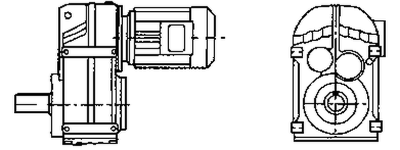
F67 Standard Foot-Mount (Solid Output Shaft)

FF67 Flange-Mount (Solid Output Shaft)

FA67 Shaft-Mounted (Hollow Output Bore)

FAF67 Flange + Hollow Bore

FAT67 Torque-Arm (Hollow Bore)

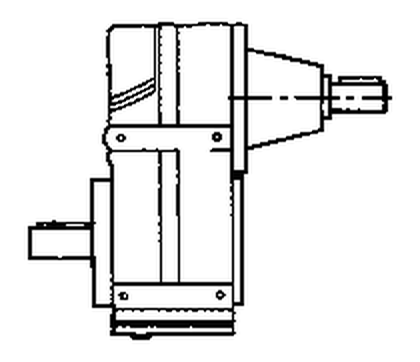
FA67-SZ Input Shaft Only
Industry Applications — Where the EP-F67 Excels
| Industry Sector | Typical Application |
|---|---|
| Slow-speed agitator drives in reactor vessels and blending tanks handling corrosive media. | |
| Travelling bridge scraper drives, sludge-thickener rakes, and drum-screen rotators in municipal plants. | |
| Rubber Compounding | Internal mixer discharge conveyors and slab-cooling table drives. |
| Ceramic Tile Plants | Kiln car pusher units and green-ware transfer conveyors requiring high starting torque. |
Application Case Study: Municipal Sludge Thickener
A municipal wastewater authority fitted EP-F67 units to four gravity-belt thickener scraper drives. After two years of continuous outdoor exposure, the units show no corrosion on the seals or housing fins, and measured energy draw is 12% lower than the specification, attributed to the high helical-gear efficiency of 96.5%.
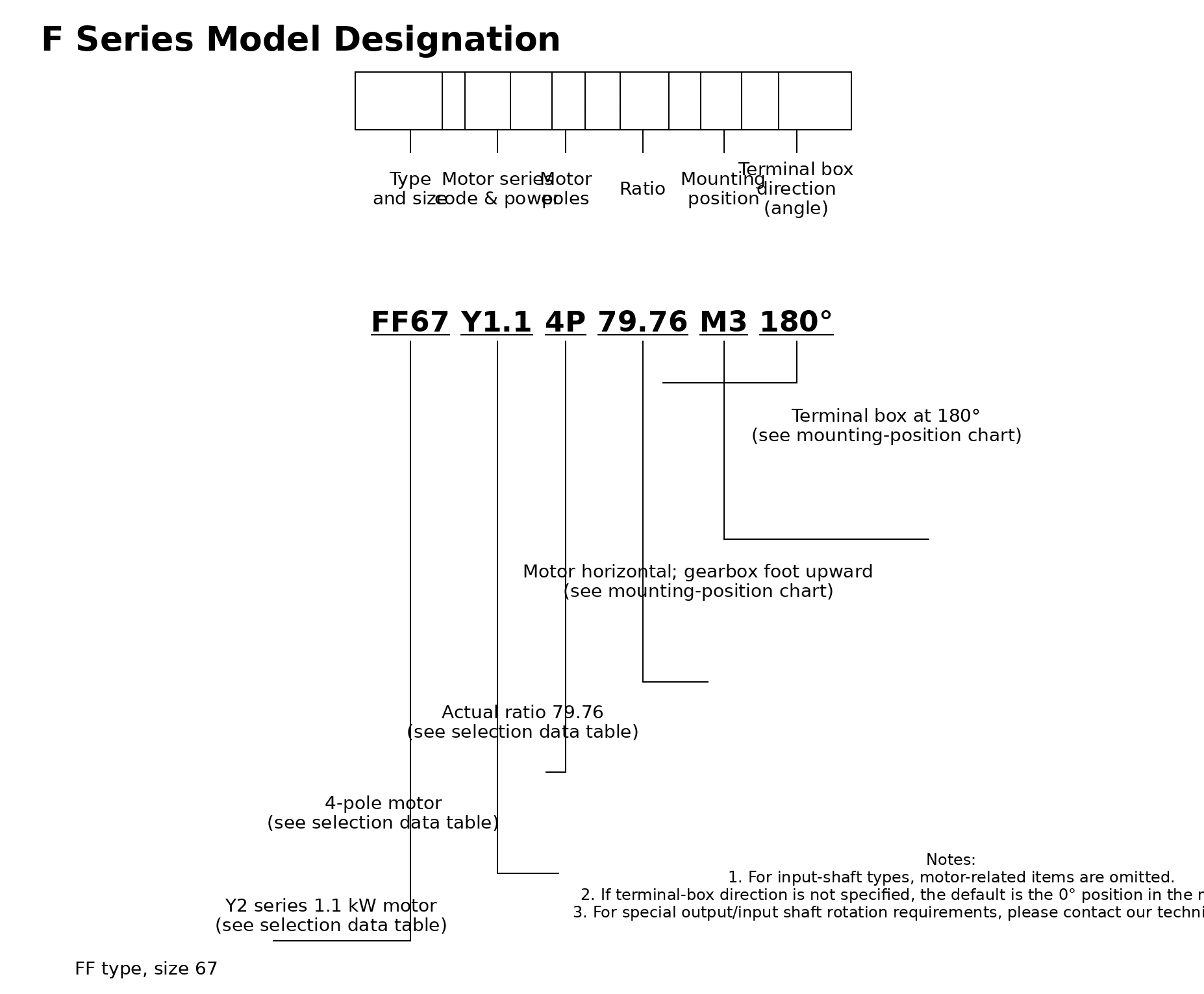
Model Designation Guide — How to Order an EP-F67
The model code contains all ordering information required for production. An example order code for a torque-arm, hollow-bore, 7.5 kW unit is:
EP – F67 – FAT – Y – 3 – 7.5 – 4P – M1
| Code Element | Meaning |
|---|---|
| EP | Brand identifier — Ever Power |
| F67 | Series and frame size |
| FAT | Structural type: torque-arm, hollow-bore output |
| Y | Motor type: Y-series IEC standard induction motor |
| 3 | Number of gear stages |
| 7.5 | Motor rated power in kW |
| 4P | Motor pole count (1,450 rpm at 50 Hz) |
| M1 | Mounting position |

Frequently Asked Questions — EP-F67
Can the EP-F67 handle shock loads from agitator starts in chemical reactors?
Yes. The EP-F67 is rated with a service factor ≥1.25 for moderate shock (Class II), and a service factor ≥1.5 is recommended for heavy shock typical of agitator starts in viscous media. Select the appropriate ratio and confirm the peak torque does not exceed 2.5× rated output torque.
What certifications does the EP-F67 carry?
Standard production units comply with ISO 9001 quality management. ATEX Zone 2 and Zone 22 variants are available for use in potentially explosive dust or gas atmospheres, with the appropriate category markings applied to the nameplate. CE marking is included as standard for units shipped to EU destinations.
How is the EP-F67 torque arm configured for the FA/FAT installation?
The FAT67 variant includes an integral torque-arm boss on the gearbox housing. A single-sided torque arm with rubber anti-vibration mounts fits directly to this boss, reacting the output torque without transmitting bending loads to the driven shaft — ideal for screw conveyor and drum-mixer applications.
What is the ordering process for first-time buyers?
New partners are welcome to order 1–5 sample units; our minimum order value is USD 1,500 and applies to combined orders across any EP product line. Standard lead time is 10–25 working days (standard configuration) or 20–45 working days (custom configurations). Contact our team via the inquiry form for a formal quotation.
Is a backstop (anti-reverse) available on the EP-F67?
A sprag-clutch backstop preventing reverse rotation is available as a factory-fitted option on FA67 and FAT67 variants. This is standard practice for bucket elevator and inclined conveyor applications where back-driving under load would cause equipment damage.
Precision Drive Technology for Demanding Industrial Processes
The EP-F67 has proven its reliability in continuous-duty chemical and wastewater installations worldwide. To discuss your specific process requirements, including corrosion-resistant housings, ATEX certification, or custom shaft configurations, reach our specialists via the inquiry form.