


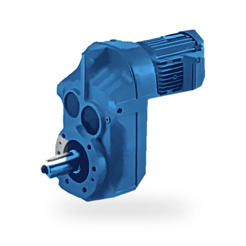
Product Overview — EP-F127 Parallel-Shaft Helical Gear Reducer
At the upper end of the F-series, the EP-F127 parallel-shaft helical gear reducer serves the heaviest stationary industrial installations: large conveyor drives in iron ore handling, offshore gas compressor auxiliaries, rolling mill table drives, and major chemical plant agitators. The three-stage precision gear train is rated at up to 12,000 N·m continuous output torque and accepts motor powers from 1.1–55 kW across ratios of 5.04–97.17.
Engineering at this scale demands rigorous tolerance management. Every EP-F127 gear set is profile-ground to DIN quality 5 or better, with flank microgeometry corrections applied to manage load distribution across the full face width. Housing bores are matched to bearing outer rings with H7/r6 interference fits confirmed at final assembly, and gear centre distances are verified with CMM-measured master gears on the production line.
Each unit undergoes a factory run-in test at rated load and speed before despatch. Test results — oil-temperature rise, vibration spectrum, and noise level — are recorded in a unit-specific test certificate supplied with the gearbox. This documentation supports both commissioning sign-off and future maintenance benchmarking. Contact our project sales team for detailed project proposals.
Technical Specifications — EP-F127
| Parameter | Specification |
|---|---|
| Gear Type | Multi-stage parallel-shaft helical gears, precision-ground DIN 6/ISO 6 |
| Number of Stages | 3-stage |
| Motor Power Range | 1.1–55 kW |
| Max Output Torque | 12,000 N·m |
| Gear Ratio Range | 5.04–97.17 |
| Output Speed Range | 15–278 rpm |
| Approximate Unit Weight | 370–520 kg |
| Max Output Radial Load | 55,000 N |
| Transmission Efficiency | ≥ 96% per stage (overall ≥ 92% for 2-stage, ≥ 88% for 3-stage) |
| Lubrication | Splash lubrication; ISO VG 220 mineral oil (factory fill) |
| Housing Material | Close-grained cast iron (HT250 / EN-GJL-250) |
| Gear Material | Case-hardened alloy steel (20CrMnTi / 20MnCr5), HRC 58–62 |
| Protection Rating | IP55 standard; IP65 optional |
| Ambient Temperature | −25 °C to +45 °C (standard lubricant) |
| Noise Level | ≤ 72 dB(A) at rated load (1 m, free-field) |
| Standards Compliance | ISO 6336, DIN 3990 gear rating; ISO 281 bearing life; CE Machinery Directive |
Structural Types & Mounting Configurations — F127 Series
The F127 series is available in multiple structural types to suit different installation geometries and driven-machine interfaces. All types share the same internal gear set and achieve identical torque and efficiency ratings; the differences lie in mounting method and output connection.
| Type Code | Description |
|---|---|
| F127 | foot-mounted, solid output shaft |
| FF127 | B5 flange-mounted, solid output shaft |
| FA127 | shaft-mounted, hollow output shaft |
| FAF127 | B5 flange + hollow output shaft |
| FAT127 | torque-arm, hollow output shaft |
| FA127-SZ | input shaft only, no motor flange |

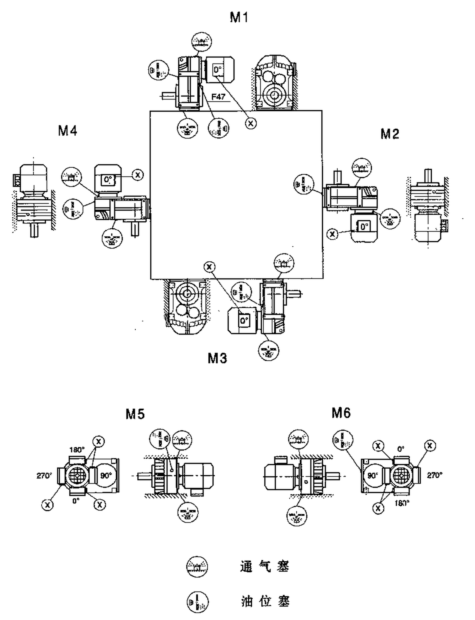
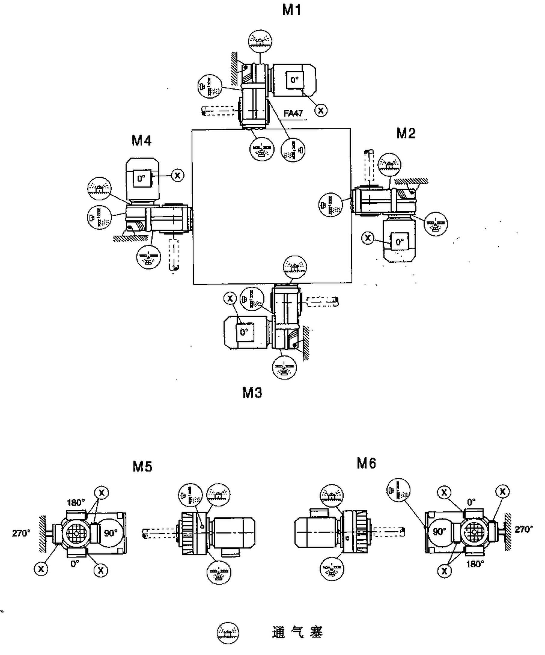
Mounting Positions M1–M6
All F127 structural types support six standard mounting positions (M1 through M6), defined by the angular orientation of the output shaft relative to the horizontal. Oil fill level and vent plug position must be adjusted for each mounting position; refer to the installation manual for position-specific fill quantities and the correct vent-plug orientation.

Key Advantages of the EP-F127
Each gear stage delivers ≥96% mechanical efficiency through precision-ground helical flanks and optimised tooth profile corrections. Compared with worm reducers of equivalent output torque, the EP-F127 typically saves 15–35% in electrical energy over the same duty cycle — a saving that often exceeds the gearbox purchase price within two years.
With up to 12,000 N·m from a housing sized for 1.1–55 kW, the EP-F127 achieves torque density competitive with bevel-helical units of the same output-shaft diameter. The case-hardened alloy-steel gears (HRC 58–62) sustain high Hertzian contact stress without case fatigue, enabling compact dimensions even at the upper end of the power range.
Bearings are selected for a minimum L10h life of 20,000 hours at rated conditions and verified by ISO 281 calculation using actual application load spectra. Precision-ground gears eliminate the geometric errors that cause micro-pitting, extending tooth-flank life to typically 40,000 hours or more when correctly lubricated.
Five standard structural types — F, FF, FA, FAF, FAT — and an input-shaft-only FA-SZ variant address virtually every machine interface geometry without custom engineering. The FA and FAT hollow-bore types eliminate external couplings entirely, reducing drivetrain length and eliminating one routine maintenance item.
Helical gear engagement produces a progressive, distributed contact zone rather than the sudden full-face mesh of spur gears. This characteristic, combined with profile-ground tooth flanks and dynamically balanced rotating components, keeps noise levels below 72 dB(A) at 1 m — important in operator-occupied environments and buildings with vibration-sensitive equipment.
The parallel-shaft geometry keeps the overall drive envelope short in the radial direction, allowing direct-couple installation in machine frames where right-angle units would require a longer cantilevered arrangement. The F127's small envelope also reduces the inertia of the stationary drive assembly, which matters in frequent-cycle indexing applications.
Structural Type Diagrams — F127 Series
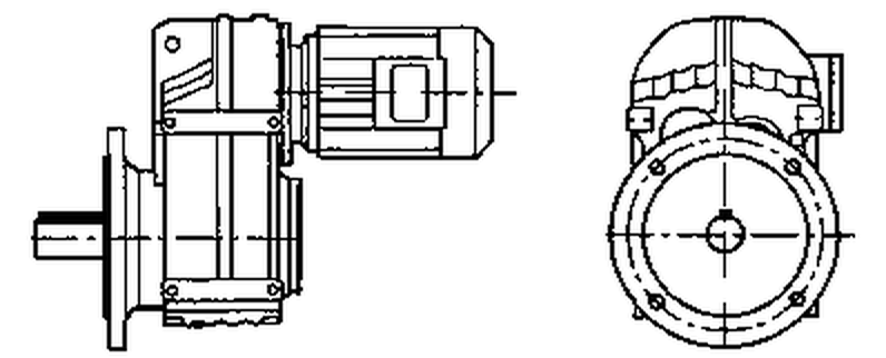
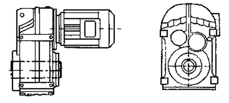
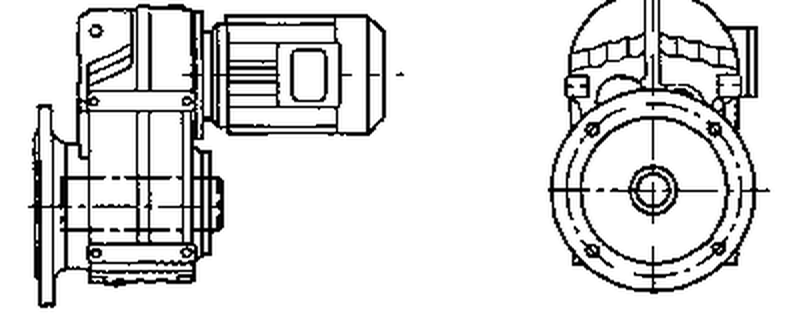
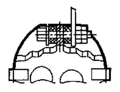
The diagrams below show the external geometry and connection interfaces for each structural type in the F127 family. Use these to confirm mounting space requirements and driven-machine interface compatibility before finalising your order.

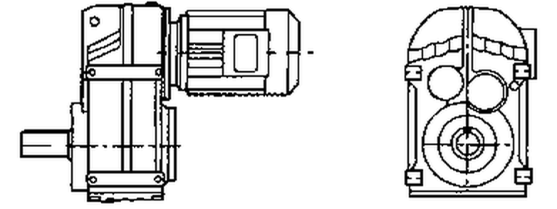
F127 Standard Foot-Mount (Solid Output Shaft)

FF127 Flange-Mount (Solid Output Shaft)

FA127 Shaft-Mounted (Hollow Output Bore)

FAF127 Flange + Hollow Bore

FAT127 Torque-Arm (Hollow Bore)

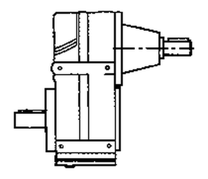
FA127-SZ Input Shaft Only
Industry Applications — Where the EP-F127 Excels
| Industry Sector | Typical Application |
|---|---|
| Heavy Metallurgy | Sinter strand pallet-car drives and converter tilting gearboxes in integrated steel works. |
| Wellhead pump jack gearboxes and offshore gas compressor auxiliary units. | |
| Large-Scale Mining | Stacker-reclaimer luffing winch drives and tripper conveyor head-end units. |
| Heavy Shipbuilding | Drydock transfer trolley drives and hull-blasting blast-pot trolleys. |
Application Case Study: Offshore Gas Compressor
A floating production unit required a compact, high-reliability auxiliary gearbox for a gas injection compressor. The EP-F127's parallel-shaft layout enabled a 35% shorter machine-room layout compared with a bevel-helical alternative, while its marinised sealing package passed a 500-hour salt-fog test without leakage.
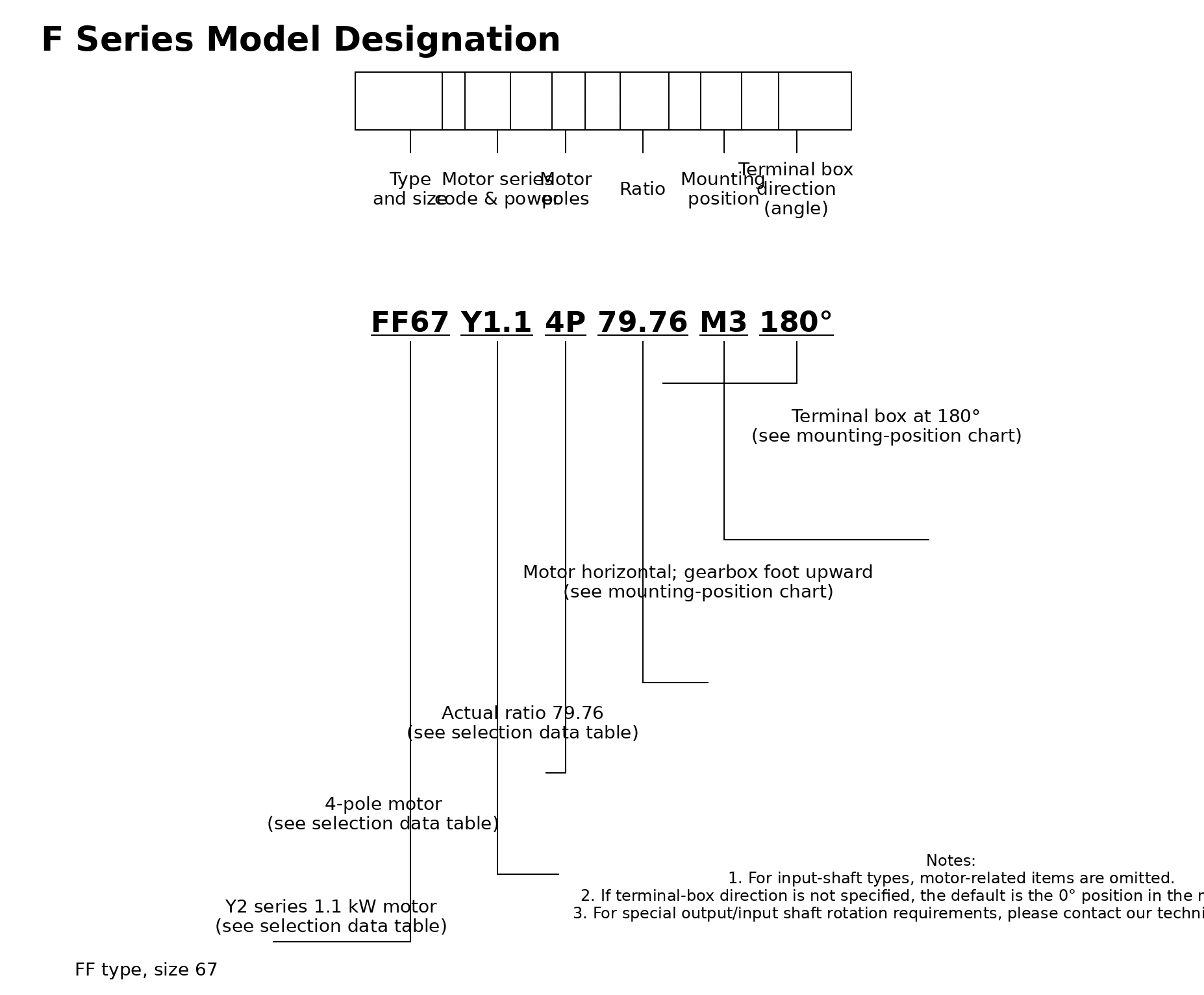
Model Designation Guide — How to Order an EP-F127
The model code contains all ordering information required for production. An example order code for a torque-arm, hollow-bore, 7.5 kW unit is:
EP – F127 – FAT – Y – 3 – 7.5 – 4P – M1
| Code Element | Meaning |
|---|---|
| EP | Brand identifier — Ever Power |
| F127 | Series and frame size |
| FAT | Structural type: torque-arm, hollow-bore output |
| Y | Motor type: Y-series IEC standard induction motor |
| 3 | Number of gear stages |
| 7.5 | Motor rated power in kW |
| 4P | Motor pole count (1,450 rpm at 50 Hz) |
| M1 | Mounting position |

Frequently Asked Questions — EP-F127
What foundation bolt pattern is used for the EP-F127 foot-mounted variant?
The F127 foot-mounted variant uses a four-bolt rectangular base pattern. Bolt hole centres and tapped depths are listed in the certified dimensional drawing, available on request. Grout pads and anti-vibration mounts sized for the unit weight (370–520 kg) are available from our accessories catalogue.
How is the oil level checked on the EP-F127?
Oil level is checked via the sight-glass or dipstick on the gearbox side face, with the unit at rest and fully cooled. EP-F127 requires approximately 18–24 litres of oil depending on ratio and mounting position. Consult the lubrication chart in the installation manual before filling.
What is the maximum ambient operating temperature for the EP-F127?
Standard units are rated for −15 °C to +45 °C ambient. For operating temperatures up to +60 °C (e.g., near furnaces), specify synthetic ISO VG 320 lubricant and confirm that the external surface temperature of the housing does not exceed 70 °C in accordance with CE safety requirements.
What is the ordering and delivery process for the EP-F127?
EP-F127 units are heavy industrial items typically ordered in project quantities. Minimum order value is USD 1,500. Single-unit samples are accepted for engineering evaluation. Lead time: 10–25 working days (standard catalogue); 20–45 working days (modified designs); project-class orders exceeding 10 units may have separately agreed delivery schedules. Trade terms include EXW, FOB, CIF, and DAP; DDP available for select destinations.
Can the EP-F127 be used as a speed increaser (step-up gearbox)?
Yes, with caveats. The EP-F127 can be run in reverse (slow shaft as input, fast shaft as output) to increase speed. However, bearing dynamic loads change, and lubrication may require redesign. Consult our applications team with your input/output speeds and loads before proceeding.
High-Torque Drive Solutions for Critical Industrial Assets
Ever Power's engineering team specialises in high-torque parallel-shaft applications where standard catalogue products need adaptation. The EP-F127 programme includes custom bore diameters, shaft keyways, special coatings, and ATEX certification. Explore our full product line at the Ever Power homepage or contact us for an application review.