The reducer is an indispensable key equipment in modern industry, widely used in various mechanical transmission systems. Understanding the working principle of the reducer not only helps to select and use the reducer correctly but also improves the operating efficiency and life of the equipment.
A Speed Reducer: What Is It?
Meaning and Purpose
A mechanical device called a speed reducer is used to increase torque and decrease speed. Through gears, worm gears, and other transmission components, it transforms the input shaft's high-speed revolution into the output shaft's low-speed, high-torque rotation.
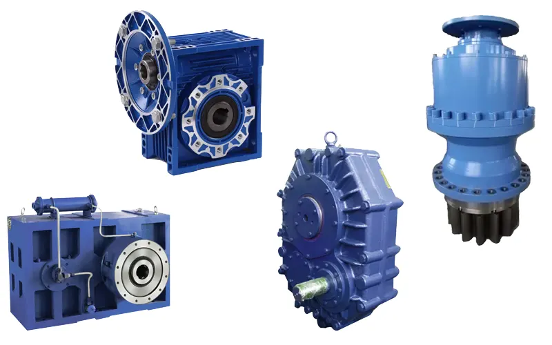
Main Types
- Gearmotors: Including cylindrical gearmotors, bevel gearmotors, etc.
- Worm Gear Reducer: Suitable for large reduction ratio occasions.
- Planetary Gearmotors: Compact structure, strong load-carrying capacity.
- Cycloid Reducer: Suitable for high-precision transmission.
Working Principle of Reducer
Basic Transmission Principle
The basic working principle of the speed reducer is to convert the high-speed rotation of the input shaft into the low-speed and high-torque rotation of the output shaft through gear meshing or worm gear transmission. The specific process is as follows:
- Input Shaft Rotation: The motor or other power source drives the input shaft to rotate.
- Gear Meshing: The gears on the input shaft mesh with the gears on the output shaft to transmit power.
- Speed Reduction: The speed reduction is achieved by combining gears with different numbers of teeth.
- Torque Increase: According to the law of conservation of energy, the torque increases as the speed decreases.
Working Principle of Gear Reducer
Gearmotors achieve speed reduction through multi-stage gearing. Each stage of gearing reduces the rotational speed by a certain amount and increases the torque accordingly. The process is as follows:
- First-Stage Gearing: The pinion on the input shaft drives the large gear to achieve the first deceleration.
- Second-Stage Gearing: The large gear drives the next pinion gear to achieve the second reduction.
- Multi-Stage Transmission: Through multi-stage gearing, the required speed and torque are finally achieved.
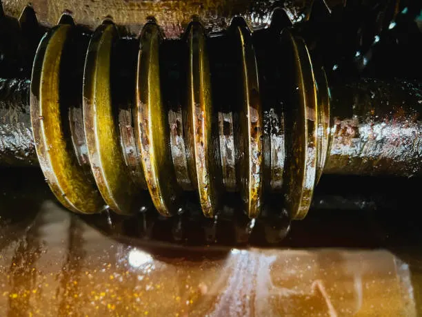
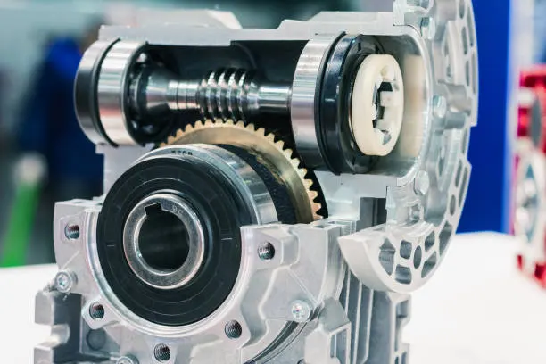
Working Principle of Worm Gear Reducer
Worm gear reducers achieve deceleration through the meshing of the worm gear and worm wheel. They are characterized by a large transmission ratio and compact structure but have low efficiency. The specific process is as follows:
- Worm Rotation: The worm on the input shaft rotates to drive the worm wheel.
- Worm Wheel Rotation: The rotation of the worm wheel drives the output shaft to rotate.
- Deceleration Effect: Due to the large ratio of the number of teeth of the worm and the worm wheel, a large reduction ratio is achieved.
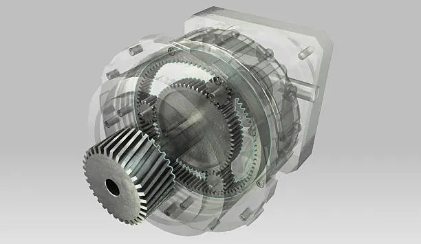
Working Principle of Planetary Gear Reducer
The planetary gear reducer achieves deceleration through the combination of the planetary wheel, sun wheel, and internal gear ring. It is characterized by a compact structure and high load-carrying capacity. The specific process is as follows:
- Sun Wheel Rotation: The sun wheel on the input shaft rotates to drive the planetary wheel.
- Planetary Wheel Rotation: The planetary wheel drives the planetary carrier by rotating between the internal gear ring and the sun wheel.
- Revolution of the Output Shaft: The output shaft rotates to accomplish deceleration due to the planetary carrier's revolution.
Speed Reducers Applications
Industrial Equipment
Reducers are frequently employed to enhance torque and decrease speed in various industrial gear, including winches, mixers, and conveyors.
Automation Equipment
In automation equipment, reducers are used to accurately control the speed and position of movement, such as in robots and CNC machine tools.
Transport
Reduction gears are also widely used in the field of transport, such as in automobiles, trains, ships, etc., for transmission systems and power distribution.
Energy
In the energy industry, gearboxes are used in wind turbines, hydroelectric generators, etc., to convert natural energy into electricity.
How to Choose the Right Gearbox?
Determine the Requirements
- Speed Requirement: Select the appropriate reduction ratio according to the required speed of the equipment.
- Torque Requirement: Select the appropriate torque output according to the size of the load.
- Installation Space: Select the appropriate size reducer according to the installation space of the equipment.
Considerations
- Efficiency: Different reducers have different efficiencies, and choosing a high-efficiency reducer can save energy.
- Lifespan: Choose a durable and reliable reducer to reduce maintenance costs.
- Cost: Choose a cost-effective reducer that meets your needs.
Maintenance and Care of the Speed Reducer
Regular Inspection
- Lubrication: Regularly check the quantity and quality of lubricant to ensure good lubrication.
- Fasteners: Check whether the fasteners are loose and tighten them in time.
- Wear and Tear: Check the wear and tear of gears, bearings, and other wear parts and replace them in time.
Common Faults and Treatment
- Excessive Noise: May be due to gear wear or poor lubrication. Check and replace the lubricant or gear.
- Excessive Temperature Rise: May be due to excessive load or poor lubrication. Check the load and lubrication.
- Ölleck: May be due to a damaged seal. Replace the seal.